First, make sure your fuel tank is less than a ¼ tank because we need to drop the fuel tank. Jack up the rear of car on both sides and put on jack stands. You will need to drop the fuel tank to get the top bolts out for the TTL. They’re like foot long bolts, and there’s only 6 inches clearance until they hit the tank and they still got 6 inches to go. You don’t need to completely remove the tank, but you will need to drop the rear corner. Slide under the car. At the REAR of the fuel tank, you’ll see one HUGE rubber line to the tank, a medium one, and two small lines all clustered together. You need to pull the huge hose and the two small ones. The medium size one has enough clearance to drop enough. You then need to support a jack underneath to give it some support and jack the jack up enough to touch the tank. Then, find the support straps. Completely remove the rear bolts on each strap. Leave the straps on the front side of the tank alone. Lower the tank with the jack. There may be an odd hose or something here or there that you may need to temporarily detach or move to get it down enough. Figure it out. Just make sure you don’t put any tension on the fuel pump wires on the top center of the tank. You’ll see them when the tank starts dropping.
OK. Take off the TTL bolts. Use the online shop manual if you seriously can’t figure this out. But basically, you’ll need a 21mm and a 17mm socket for each bolt/nut combo. And then you’ll need I believe a 14mm box wrench and an allen wrench to take off the anti-sway bar link.
When you get the TTL’s out, you’ll notice three of the four bushings look pretty much the same with about 1/8” sticking out one side and ¼” sticking out the other side. However, the 4th bushing will have ¼” out one side and then the center rod sticks out like another two inches the other direction. Make a note now which end is which end and what each looks like. Refer to the other side of the car if you need to reference.
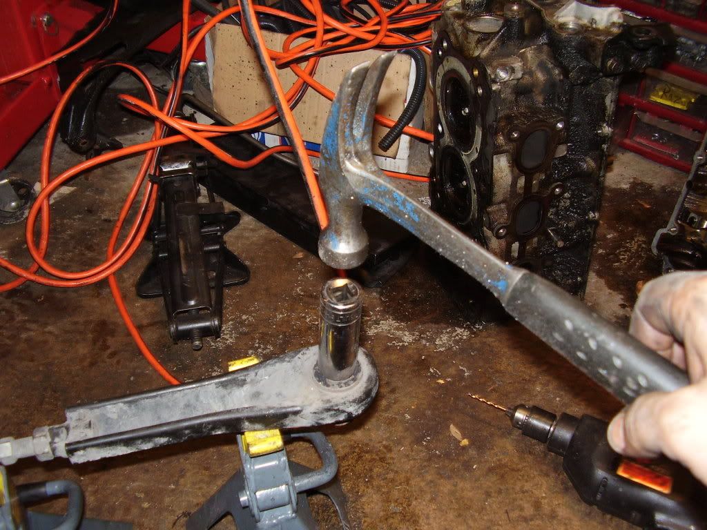
For the 3 bushings that look the same ….. it will be the same procedure. First, drill out along the outer rubber layer all the way around the perimeter, with as many holes as you can make. I believe I used both 7/64" and 3/32" drill bits. You'll probably break a few in the process .... titanium or not, so buy like 5 cheapie bits.

Once, you’ve got as many holes as you can make, and making sure the holes go all the way through ….. you’ll probably want to use a flathead screwdriver as a punch along the seam you were drilling on and try to break the rubber loose even more than the drilling did. Then, when you’ve broken as much loose as you can, it’s time to press the bushing out.

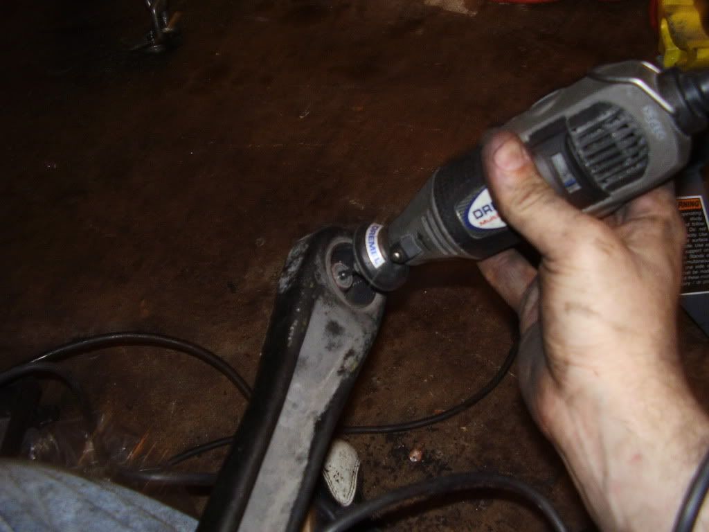
When you get the bushing out, clean up the inside of the TTL hole with a Dremel with a 60grit sanding bit. You don’t need to get every last spec of rubber out. In fact, leaving a SLIGHT bit helps hold the new bushing in. But you’ll want to get high spots down until the Energy bushing slides in with a medium amount of force.

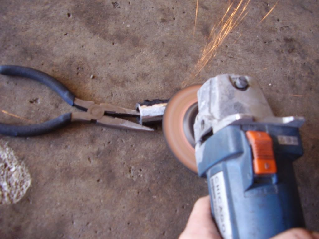
Then, you’ll nee to get the bushing material you just pressed out off the metal rod you’re going to reuse. There are two metal half-jackets around the rod enshrouded in rubber. You need to get the metal half-jackets off. I use a flathead as a chisel at the seams of the metal half-jackets.

Then, You’re going to need to get the last bit of rubber off the metal rod. You need every last bit of rubber off, or it’ll keep the rod from going into the new bushing.

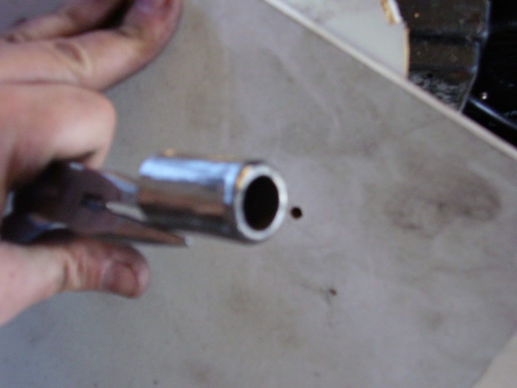
You’ll also want to grind a 45 degree bevel on one side so that when you start pressing it into the bushing, it’ll wedge its way in and not get stuck as easy going in.

Then, take the Energy half-bushings you’ve got. For each of the holes in the TTL, you’re going to grind the lip on top down to about half thickness. Then, on that bushing and another bushing with an unmolested lip, you’re going to grind down the height from the side with no lip so that both will slide into the TTL and when both in together, both can sit flush down to the lips. Once this is accomplished, it’s time to start pressing the center rod in.
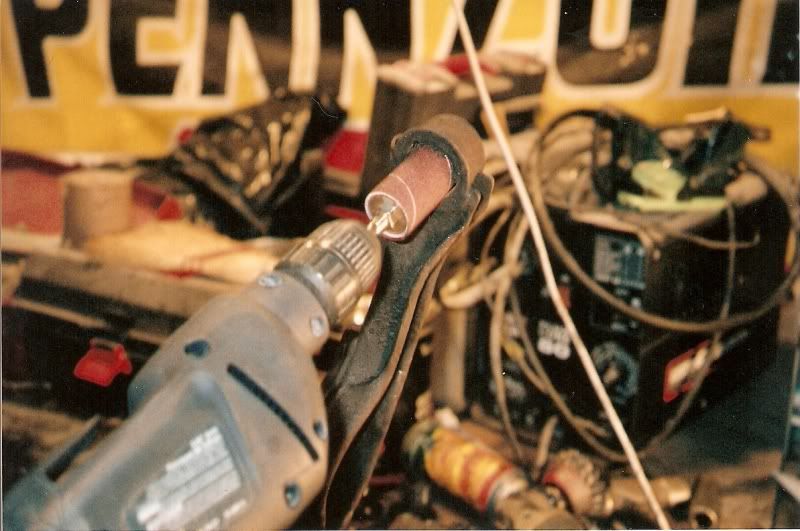
First, the inner diameter of the bushings will probably be too small for the center rods you just cleaned up. Just take a Dremel with a 60 grit sanding drum and start sanding the inner rim down until you can start getting that rod going in them with a hammer. If you grind so much down that you can press it in with your hand, you overdid it. The harder it is to get these into the hole, the better the bushing will be forced into the TTL hole. So like sex with a college girl, tighter is better. You’ll remember earlier, I pointed out that the stock TTL had one side that had about 1/8” sticking out and another side had ¼” sticking out? Well you better have remembered which side was which, because remember the Energy bushing you just grinded half the thickness of the lip? That’s going to go on the 1/8” side to try to maintain as much of the stock geometry as possible.
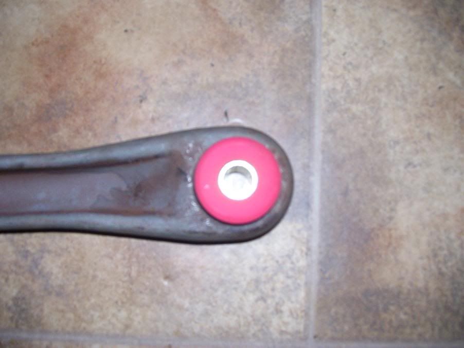
When we get to the 4th TTL hole, the proceedure will be the same. One Enegry lip will be ground
Down to half. But when you grind the center rod down, you want to only grind up to the beginning of the old bushing. There will be a definite lip, and you want to maintain that. I would actually recommend to make the lip even deeper by actually griding into this rod to get some thickness off. This will alleviate the step where you need to Dremel the inside of the Energy bushing. The reason it’d be better to have this lip be as high as possible, is because this is the one side that we can’t put a washer to help hold the Energy bushing in. That lip is all that’s going to hold that bushing on. The half-lip bushing will go on the offset side to maintain geometry again. This is what assembly should look like:

Then, don’t be a freaking slob. You’ve got the pieces off, clean them up with a little sandpaper and put a fresh coat of black paint on them. Use the rust preventative kind. I used a semi-gloss rust-eater paint. This will keep the alignment guy from having to vomit when he gets under your car.

Before installing, all that pounding on the center rods have messed up the rod ends a little bit. So before installation, you’ll need to take the Dremel with a thin grinding bit and clean out the inner diameter until the bolt will fit in it comfortably again.
Now, install the way you took it out. You’ll be reusing the 4 washers that were on the bolts to begin with at the extreme ends before. But, you’ll also have gone to the hardware store to buy 6 more washers of similar diameter with similar diameter center hole. Like said, you can’t use a washer on that one offset side. Every single other of the 7 half-bushing ends should have a washer helping press in the Energy bushings. Lube up both sides of the washers with grease, and the inner diameter of the old rod. Tighten everything up once all the bolts are on, and put your fuel tank back.
After driving for a couple days, you'll want to take it to an alignment shop and get at least the rear end toe adjusted. Your camber should be unaffected, though. Just the toe NEEDS to be looked at. A full 4 wheel alignment couldn't hurt, though, if you haven't had one in a while.


 Jeff Aycan - Site & Forum Owner/Administrator