Trying to gauge interest in cheep AF gauge buy.

4-Cyl. Technical/Performance Discussions
Post Reply
Bochek
Regular Member
Posts: 1704
Joined: December 31st, 2005, 5:54 pm
Location: Burlington + Grimsby, Ontario, Canada
Contact:

Trying to gauge interest in cheep AF gauge buy.

Post by Bochek »

I am planing on makeing a AF gague for myself and while im at it im wondering if anyone else would want one.

The following image is a comparision of the one i will be making (left) compared to a commercial unit (right)

Image

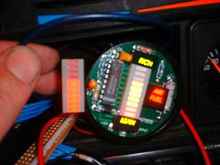
you will have to devise your own way of mounting the graph. The electronic circuits are seperated from the actual graph, joined by some wires. so you can hide away the circuitry and just show the gague, i can calibrate the gage from any voltage below one volt (no lights are on) to 1 volt (all lights are on).

Unfortunatly this will not work with a wide band o2 sensor.

I can make the gagues in eather yellow, green or red bar graphs, and you can select between a bar or dot type graph, (in bar style all the lights below the current reading are turned on, in dot style just the current reading is turned on.

If you would like one the cost will be $30 canadian + shipping

For an extra $5 i will put the electonic compents inside a little plastic case so you dont have to insulate them yourself.

Let me know, if i get enough interest i will make these.


If any admin needs to talk to me about this, please pm me.

Thanks,
Bochek


Interested:

Handle/Case/Color/Voltage Range/Dot or Bar

1) Trevo123 /Y/G/0-1/B
Adam Bochek's 93 1.6L SOHC http://www.bochek.ca/car.gif
User avatar
ariesdude
Regular Member
Posts: 1244
Joined: August 4th, 2005, 2:43 pm
Contact:

Post by ariesdude »

Is it just a voltmeter with the LED bar instead of digits? If yes it may not work as an A/F gauge. If you have an actual A/F gauge circuitry then never mind the following -

The output from the O2 sensor does not stay at low or high (for lean or rich) - it oscillates between 0 and 1 many times a second depending on the combustion. The O2 sensor testing procedure says that if the O2 reading stays constant (after warmup) then the sensor needs to be replaced. I hooked up my digital volt meter to the O2 Sensor and i could not get a constant reading from it even in the AC mode. I think a proper A/F gauge averages the number/direction of transitions - an ideal A/F gauge would also get input from MAF and Injector pulse widths.
94 Mx-3 Precidia
1.8L 4Cyl DOHC newGen BP (used to be B6DE) ATX
http://www.mx-3.com/phpbb2/viewtopic.php?t=54032
http://www.cardomain.com/id/ariesdude
Bochek
Regular Member
Posts: 1704
Joined: December 31st, 2005, 5:54 pm
Location: Burlington + Grimsby, Ontario, Canada
Contact:

Post by Bochek »

the circuitry inside the a/f gague buffers out the "pulses" and essentially gives you the adverage of them, giving you your a/f reading.

you can see here that the chip i use and the chip in the readily available commercial unit is identical

Image

Bochek
Adam Bochek's 93 1.6L SOHC http://www.bochek.ca/car.gif
User avatar
ariesdude
Regular Member
Posts: 1244
Joined: August 4th, 2005, 2:43 pm
Contact:

Post by ariesdude »

I am not trying to do any unnecessary criticism - I am just trying to clear some doubts. Obviously once you get this built up and working just like the commercial gauge - all comments would be useless. But hey, i might learn something new in this process.

Anyways ....

As far as i know - The chip LM3914N is a LED bar display driver - not a volatger "buffer" or integrator. Atleast a simple RC circuit is needed to inegrate the i/p voltage. And a simple RC circuit is not accurate by any means. Looks like the commercial board in the picture may not have an RC circuit either and probably the leds just jump up and down constantly.

I read up on some commercial units like autometer - they all seem to be the same thing - connecting an voltmeter to the O2 sensor o/p - which means they all jump around crazy. If its good for most people, sometimes its good for me too.

Personally i would prefer the O2 signal integrated over a small period of time (say maybe 2 secs) - which would tell me if the engine has been running lean or rich on average for that 2 secs. That would be much better than trying to keep track of jumping leds changing directions multiple times per second (depending on rpm).
94 Mx-3 Precidia
1.8L 4Cyl DOHC newGen BP (used to be B6DE) ATX
http://www.mx-3.com/phpbb2/viewtopic.php?t=54032
http://www.cardomain.com/id/ariesdude
Bochek
Regular Member
Posts: 1704
Joined: December 31st, 2005, 5:54 pm
Location: Burlington + Grimsby, Ontario, Canada
Contact:

Post by Bochek »

agreed. the chip is a led bar/dot graph driver,

i believe, but i am still yet to experiment with this, that a small capacitor and a diode will eliminate the "jumping up and down" in the same what that a capicitor iliminates bass in speakers.

once i get all my parts i will experiment with this and let you know the results.

Bochek
Adam Bochek's 93 1.6L SOHC http://www.bochek.ca/car.gif
User avatar
Custommx3
Site Administrator
Posts: 8391
Joined: November 7th, 2000, 2:01 am
antispam: ~SPAM*SUX~
Location: Lat 35.1N Lon -90W
Contact:

Post by Custommx3 »

I understand your just gauging interest, but remember,, not group buys w/o jeffs permission. (webmaster @ mx-3.com)
Bochek
Regular Member
Posts: 1704
Joined: December 31st, 2005, 5:54 pm
Location: Burlington + Grimsby, Ontario, Canada
Contact:

Post by Bochek »

i am well aware of the rules and will be sending a email to him before anything is sold at all.

my circuits still being developed as you can see from the above discussion, so no worries for a week or so yet.

Bochek
Adam Bochek's 93 1.6L SOHC http://www.bochek.ca/car.gif
User avatar
BuGS
Regular Member
Posts: 1521
Joined: May 5th, 2004, 2:01 am
Location: East Wenatchee, WA, USA
Contact:

Post by BuGS »

ariesdude wrote:I am not trying to do any unnecessary criticism - I am just trying to clear some doubts. Obviously once you get this built up and working just like the commercial gauge - all comments would be useless. But hey, i might learn something new in this process.

Anyways ....

As far as i know - The chip LM3914N is a LED bar display driver - not a volatger "buffer" or integrator. Atleast a simple RC circuit is needed to inegrate the i/p voltage. And a simple RC circuit is not accurate by any means. Looks like the commercial board in the picture may not have an RC circuit either and probably the leds just jump up and down constantly.

I read up on some commercial units like autometer - they all seem to be the same thing - connecting an voltmeter to the O2 sensor o/p - which means they all jump around crazy. If its good for most people, sometimes its good for me too.

Personally i would prefer the O2 signal integrated over a small period of time (say maybe 2 secs) - which would tell me if the engine has been running lean or rich on average for that 2 secs. That would be much better than trying to keep track of jumping leds changing directions multiple times per second (depending on rpm).
Well the reason For the random jumping is because I narrow-band O2 only measures a very little amount. And trust me, if you actually used it like I do I need to know exactly when I am leaning out to the 100th RPM
User avatar
ariesdude
Regular Member
Posts: 1244
Joined: August 4th, 2005, 2:43 pm
Contact:

Post by ariesdude »

I have been reading up on O2 sensor because i am thinking about a 4 wire conversion. Here is a good gist of what i read -

http://www.mr2.com/TEXT/O2_Sensor.html
How does an O2 sensor work?
An Oxygen sensor is a chemical generator. It is constantly making a comparison between the Oxygen inside the exhaust manifold and air outside the engine. If this comparison shows little or no Oxygen in the exhaust manifold, a voltage is generated. The output of the sensor is usually between 0 and 1.1 volts. All spark combustion engines need the proper air fuel ratio to operate correctly. For gasoline this is 14.7 parts of air to one part of fuel. When the engine has more fuel than needed, all available Oxygen is consumed in the cylinder and gasses leaving through the exhaust contain almost no Oxygen. This sends out a voltage greater than 0.45 volts. If the engine is running lean, all fuel is burned, and the extra Oxygen leaves the cylinder and flows into the exhaust. In this case, the sensor voltage goes lower than 0.45 volts. Usually the output range seen seen is 0.2 to 0.7 volts. The sensor does not begin to generate it's full output until it reaches about 600 degrees F. Prior to this time the sensor is not conductive. It is as if the circuit between the sensor and computer is not complete. The mid point is about 0.45 volts. This is neither rich nor lean. A fully warm O2 sensor *will not spend any time at 0.45 volts*. In many cars, the computer sends out a bias voltage of 0.45 through the O2 sensor wire. If the sensor is not warm, or if the circuit is not complete, the computer picks up a steady 0.45 volts. Since the computer knows this is an "illegal" value, it judges the sensor to not be ready. It remains in open loop operation, and uses all sensors except the O2 to determine fuel delivery. Any time an engine is operated in open loop, it runs somewhat rich and makes more exhaust emissions. This translates into lost power, poor fuel economy and air pollution. The O2 sensor is constantly in a state of transition between high and low voltage. Manfucturers call this crossing of the 0.45 volt mark O2 cross counts. The higher the number of O2 cross counts, the better the sensor and other parts of the computer control system are working. It is important to remember that the O2 sensor is comparing the amount of Oxygen inside and outside the engine. If the outside of the sensor should become blocked, or coated with oil, sound insulation, undercoating or antifreeze, (among other things), this comparison is not possible.
94 Mx-3 Precidia
1.8L 4Cyl DOHC newGen BP (used to be B6DE) ATX
http://www.mx-3.com/phpbb2/viewtopic.php?t=54032
http://www.cardomain.com/id/ariesdude
User avatar
ariesdude
Regular Member
Posts: 1244
Joined: August 4th, 2005, 2:43 pm
Contact:

Post by ariesdude »

Bochek wrote:agreed. the chip is a led bar/dot graph driver,

i believe, but i am still yet to experiment with this, that a small capacitor and a diode will eliminate the "jumping up and down" in the same what that a capicitor iliminates bass in speakers.

once i get all my parts i will experiment with this and let you know the results.

Bochek

Well, here's my 2 cents about diode and capacitor -

The diode probably will not do anything here because there is no polarity reversal in the signal (unlike audio speakers which might produce a reverse voltage because of the coil moving in a magnetic field).

A capacitor acts as a filter - it filters out certain frequencies depending on the capacitance value. That is probably not a good idea for measurement - the device should not filter out anything - it should get an average of the signal over a very short period of time. That requires an integrator circuit.
Some examples -
http://www.phys.unsw.edu.au/~jw/RCfilte ... integrator
http://www.tpub.com/content/neets/14181 ... 81_199.htm
94 Mx-3 Precidia
1.8L 4Cyl DOHC newGen BP (used to be B6DE) ATX
http://www.mx-3.com/phpbb2/viewtopic.php?t=54032
http://www.cardomain.com/id/ariesdude
Bochek
Regular Member
Posts: 1704
Joined: December 31st, 2005, 5:54 pm
Location: Burlington + Grimsby, Ontario, Canada
Contact:

Post by Bochek »

ariesdude wrote:
Bochek wrote:agreed. the chip is a led bar/dot graph driver,

i believe, but i am still yet to experiment with this, that a small capacitor and a diode will eliminate the "jumping up and down" in the same what that a capicitor iliminates bass in speakers.

once i get all my parts i will experiment with this and let you know the results.

Bochek

Well, here's my 2 cents about diode and capacitor -

The diode probably will not do anything here because there is no polarity reversal in the signal (unlike audio speakers which might produce a reverse voltage because of the coil moving in a magnetic field).

A capacitor acts as a filter - it filters out certain frequencies depending on the capacitance value. That is probably not a good idea for measurement - the device should not filter out anything - it should get an average of the signal over a very short period of time. That requires an integrator circuit.
Some examples -
http://www.phys.unsw.edu.au/~jw/RCfilte ... integrator
http://www.tpub.com/content/neets/14181 ... 81_199.htm

the diode was to prevent the capicitor feeding back into the computer and confusing it.

as for the capicitor, if there is volatage in, then there must be voltage out right? So that means that the voltage out will be equil to the adverage of the volage in, over a certain periode of time. again the diode affects this because it stops the power from leaving the capicitor in the reverse direction (back to the o2 or computer)

I will have to do some research on that intergrator circuit.

I will hopefully be experimenting with this this weekend if i get time.

Bochek
Adam Bochek's 93 1.6L SOHC http://www.bochek.ca/car.gif
Bochek
Regular Member
Posts: 1704
Joined: December 31st, 2005, 5:54 pm
Location: Burlington + Grimsby, Ontario, Canada
Contact:

Post by Bochek »

This looks exactly like the circuit im describing, only without a diode.

and the resister in that circuit will cause the exact opposite signal then what we want, with that resister, the signal will never change.

Bochek
Adam Bochek's 93 1.6L SOHC http://www.bochek.ca/car.gif
User avatar
corbanbrook
Regular Member
Posts: 106
Joined: January 22nd, 2006, 9:53 am
Location: Kitchener, Ontario, Canada

Post by corbanbrook »

I want one.
92 MX-3 1.6L 4 Cyl SOHC
MPG: 21.5city/38hwy
Bochek
Regular Member
Posts: 1704
Joined: December 31st, 2005, 5:54 pm
Location: Burlington + Grimsby, Ontario, Canada
Contact:

Post by Bochek »

still doing some testing on these, il get back to you guys about it on monday.

Bochek
Adam Bochek's 93 1.6L SOHC http://www.bochek.ca/car.gif
Post Reply

Return to “4-Cyl. Technical/Performance”