These instructions are designed for an Integra, however, they can be used for a Civic with too! The only difference are the way the pipes connect! (i know its a civic but its good for anycar)
I've made custom turbo kits for a while now. Why waste $500 for Intake and Headers when you can drop down another $500 and make your own CUSTOM TURBO KIT and push a lot more horsepower, plus get the respect from people on the street when you whoop a 4.6 Liter Mustang!
The great thing about building a custom turbo kit is that you can buy the parts peice by peice at a time, rather then buying a whole kit and waste all your money at once and go broke all at once!
Before we start on the installation, please inspect the picture that I've provided. Each part is individually labeled by a number. The picture will also give you a jist of how a turbo system works! I will go through each item one by one to show you how they work. Once you understand how it works, then we will being building our custom turbo kit! And the thing is, all turbo kits mainly consists of just "pipes". If you look at the pic, notice how SIMPLE a turbo kit is! It's mainly just "pipes"!
So next time when you hear someone shedding out $3000-$3500 for a turbokit, laugh at their face because they are throwing money out of their pockets. With the other $2000 that you save, you can use that money to build your motor to handle 16+ PSI on the streets. Or use that money for a new paint job or whatever you wish!
<img src="http://www.cse.uconn.edu/~yelevich/turbo\turbo2.jpg" alt=" - " />
1. This is the wastegate. It is an external one that connects to the turbo manifold. The exhuast gases from the turbo manifold blows into the turbo and keeps on blowing. The turbo keeps on spinning and spinning and you get more and more boost! But you don't want too much boost or else your engine will blow up! (Too much boost = too much power = pistons can't handle this power = goodbye motor! ).
So how do we regulate the turbo so that it does not overspin? We have a wastegate. The wastegate sees how much boost you have in your engine. If you have it set at 7 PSI, when the wastegate sees 7 PSI, it will open up and send the exhaust gases AWAY from the turbo so the turbo does not keep spinning!
Imagine you have a windmill and you blow on it. It will spin and spin and spin. However, if you put a sponge in front of your mouth, the windmill will slow down. Thats exactly what the wastegate does. It slows down the air flow from the exhaust.
2. Turbo manifold/Turbo Header. This is the 2nd most important thing of a turbo system. It collects the exhaust gases from all 4 exhaust ports and reroutes those exhaust gases into one "big port". To explain this a little bit easier, imagine you have four straws. Imagine four people have a straw and they each blow on theirs. And then you put the ends of the straw together, voila! More efficient! Same concept with the turbo manifold.
3. Turbo, the heart of the system. Also known as the "Air Pump". Now that you have those exhaust gases from the exhaust ports, you shoot those exhaust gases into the exhaust turbine, which spins the compressor turbine. To understand the turbo, imagine you had one of those windmills. And you blow on it. The blade spins. Same concept with the turbo, except you have exhuast gases blowing on it. And imagine you connect another windmill to it. If you blow on one windmill, the other windmill will also spin. The one that you blew on, is equivalent to the "exhause turbine" on the turbo. And the one that spins along is equivalent to the "compressor turbine" on the turbo. The compressor turbine sucks in air and compresses it and pumps air out of it down into Pipe #5 (Goto 5. )
The oil needs turbo to lubricate its bearings! Without oil, the turbo will overheat. Imagine you have a bicycle wheel turning at 300 RPMS. The bearings inside will not overheat because the friction from 300 RPMs (Revolutions per minute) is nothing compared to that of a turbo. Turbos run up to 60,000 RPMs. If a bicycle wheel spun that fast, the bearings would overheat from friction and stuff would melt fast! Now imagine you sprayed oil on those bearings while its spinning at 60,000 RPMs. Much better because the heat is carried away by the oil and also the oil lubricates the bearings and causes LESS friction which means LESS heat. Same concept with the turbo. Turbos LIVE on oil!
4. Downpipe. Now that you have the exhuast gases blowing through the exhaust turbine, where does it go? It goes into the exhaust system. And to do that, the downpipe connects to the turbine side and then the other end of the downpipe makes a funny "U" turn and connects to the cat convertor. Easy as that! If you get a bigger downpipe, your turbo will spool up faster. However, if you decide to get a 3 inch downpipe, it will not clear your Air conditioner.
5. Now that the turbo is pushing air/Pumping out air, we need to "capture" this air and send it to the throttle body/intake manifold for the motor to use this pressurized air. To use this useful air, we have to send it through a bunch of pipes! This is a pipe and the air goes down, then connects to pipe #6.
6. Pipe #6 is a U bend, it makes a U bend and then connects to the intercooler (#7)
7. When you compress air, it gets HOT! If you don't believe me, have you ever touched an air pump after you pump your tires? Most of that heat is from the compressed air. And the other is from friction.
So how do we cool this hot air? We send it through the intercooler, the radiator looking thing! Intercoolers work almost like radiators except you send air through it. With the intercooler, it will cool the air a LOT.
8. Now, after the air leaves the intercooler, it goes into pipe #8 and makes a U bend, the goes into pipe #9.
9. The air from pipe #8 now enters this pipe and then the air goes into the intake manifold for your engine to use this useful compressed air.
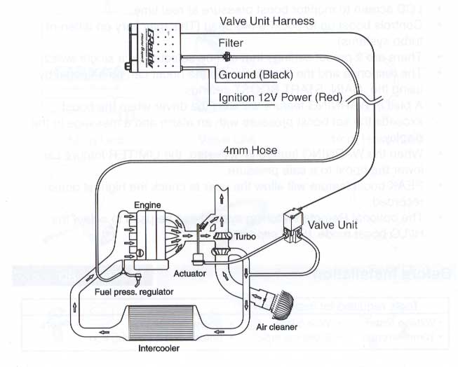
10. The blow off valve. This is the device that gives you the nice "PsssssssHHH!" sound when you let go of the gas while under boost. Not just that, it lets your turbo live longer. Why is that? Imagine you had a peice of straw. And pretend that you are a turbocharger. Blow through the pipe. Easy right? Now imagine you cover the end of it. It is very hard to blow right? By covering the end of the peice of straw, that is EXACTLY like closing the throttle plate on the throttle body. Because when you let go of the gas, the throttle plate closes.
Now, imagine you had a mini blow off valve on the straw. So that everytime you put your finger/cover the end of the straw, the blow off valve opens. So the air goes through there. Now it's easier for you to blow! And since its easier, that must mean its easier on the turbocharger! Which means longer lasting turbo!
<img src="http://www.cse.uconn.edu/~yelevich/turbo/t5.jpg" alt=" - " />
11. FMU. FMU stands for Fuel Management Unit. You will definetly need this because it adds more fuel into your cylinders when you boost. If you force more air into the cylinders via a turbo, you must add more fuel! And how do we add more fuel? There are a couple of methods. We can make the injectors shoot in more or we can increase the fuel pressure. For now, lets ignore the first method. And focus on the second method because that's what we will be using!
All B series motors are fuel injected and use a fuel rail. The fuel rail is always under pressure so that when the injectors open, the fuel shoots into the cylinders! What we can do is, increase the pressure so that it shoots more fuel into the cylinders. To make it easier to understand, imagine you had a water hose with nothing attached to the end of it. Now, imagine you squeeze the end of it, more water shoots out! Thats because you increased the pressure.
The FMU does the same thing! It "squeezes" the fuel lines to increase fuel pressure.
Without an FMU, your motor will blow up for sure! All FMUs have ratings, such as 12:1 or 8:1. What that means is, if its a 12:1, it will raise fuel pressure 12 PSI per 1 PSI of boost. So if you boost 7 PSI, then it will raise the fuel pressure to 7 X 12 = 84 PSI. When the fuel pressure is raised, more fuel is added into the cylinders. Easy concept.
Now you get how a turbo system works right? Lets review.
1. Exhaust gases from the turbo is blown into the turbo.
2. The turbo is like a pump, it uses the exhaust gases (free energy) to pump air.
3. This pumped air is then blown into some pipes that connect to the intake manifold which forces the air into the cylinders.
4. This pumped air from the turbo is HOT, so we use an intercooler to cool down this air slighty before it enters the engine.
5. The blow off valve is used to relieve pressure from the turbo when you let go of the throttle when under boost.
Ok, one more thing! Lets look at another "turbo kit" picture:
<img src="http://www.cse.uconn.edu/~yelevich/turbo/t11.jpg" alt=" - " />
All the parts that I crossed out, you do not need! Also, notice how SIMPLE a turbo kit is...it's mainly just pipes that you can buy from your Auto store or Home depot! So now you know what a turbo kit really is...it's really just pipes and a big fat hairy turbo!
1. Downpipe
2. Turbo Manifold
3. Turbo
4. Silicone hoses/Clamps
5. Intercooler
6. Various Pipes
7. Oil line for turbo and various fittings for check valves, oil return etc...
8. Blow off valve
9. Wastegate
Now, check out this picture, which is a zoom up of a manifold, turbo and wastegate:
<img src="http://www.cse.uconn.edu/~yelevich/turbo/t12.jpg" alt=" - " />
1. A Beautiful Tial Wastegate
2. Turbo Manifold
3. Big Hairy T3/T4 Turbo!
Now that you understand how a turbo system works, lets build our custom turbo kit! Below are the parts that you will need to build a typical turbo kit for a B series motor for an Integra. However, this will also work with Si's, Preludes, CRV's, Civics with some slight modifications of the turbo pipes! slight modifications = cutting with a saw. How hard is it to cut? hehe
Turbo Kits 101
-
monty73741

- Forum Moderator
- Posts: 2651
- Joined: February 11th, 2001, 2:01 am
- Location: baltimore,md usa
- Contact:
Turbo Kits 101
Jason Danaher
Please Help Support MX-3.com
MX-3.com Online Store - http://www.mx-3.com/osv3
CafePress - http://www.cafepress.com/mx3com
Please Help Support MX-3.com
MX-3.com Online Store - http://www.mx-3.com/osv3
CafePress - http://www.cafepress.com/mx3com
Re: Turbo Kits 101
interesting.... 
Derek Van Horne MX-3.com Member # 33

94 MX-3 Silver Stone Metallic CAR is SOLD
Car Domain Web page MX-3
Car Domain Web page SRT-4
94 MX-3 Silver Stone Metallic CAR is SOLD
Car Domain Web page MX-3
Car Domain Web page SRT-4
-
Juans_93_MX3
- Senior Member
- Posts: 2220
- Joined: October 17th, 2004, 2:01 am
- Location: SLC, Utah
Re: Turbo Kits 101
This should go on one of the FAQ forums 
Thanks for this thread.
<small>[ November 06, 2004, 11:53 PM: Message edited by: Juan's MX3 ]</small>
Thanks for this thread.
<small>[ November 06, 2004, 11:53 PM: Message edited by: Juan's MX3 ]</small>
2008 Mazda 3
1993 MX3 GS
KLZE, Fidanza flywheel, KL31 CAMs, South Bend Stage I Clutch, Pacesetter STS, SS AutoChromes, Magnaflow muffler, 2.25' Exhaust, CAI, Blaster Coil HEI, KLDE Valvetrain, 5 Speed Swap
1993 MX3 GS
KLZE, Fidanza flywheel, KL31 CAMs, South Bend Stage I Clutch, Pacesetter STS, SS AutoChromes, Magnaflow muffler, 2.25' Exhaust, CAI, Blaster Coil HEI, KLDE Valvetrain, 5 Speed Swap
-
Juans_93_MX3
- Senior Member
- Posts: 2220
- Joined: October 17th, 2004, 2:01 am
- Location: SLC, Utah
Re: Turbo Kits 101
By the way, I love your sig (to the maker of this thread)
2008 Mazda 3
1993 MX3 GS
KLZE, Fidanza flywheel, KL31 CAMs, South Bend Stage I Clutch, Pacesetter STS, SS AutoChromes, Magnaflow muffler, 2.25' Exhaust, CAI, Blaster Coil HEI, KLDE Valvetrain, 5 Speed Swap
1993 MX3 GS
KLZE, Fidanza flywheel, KL31 CAMs, South Bend Stage I Clutch, Pacesetter STS, SS AutoChromes, Magnaflow muffler, 2.25' Exhaust, CAI, Blaster Coil HEI, KLDE Valvetrain, 5 Speed Swap
-
mxprecidia
- Regular Member
- Posts: 339
- Joined: January 9th, 2004, 2:01 am
- Location: Philly
- Contact:
Re: Turbo Kits 101
so u dont need an intake filter since u crossed it out?
also, can u have headers if u want turbo...how would that work
also, can u have headers if u want turbo...how would that work
www.illegalCustoms.com
Tri-State Area Car Club
Tri-State Area Car Club
-
babyblueMX3

- Supporting Member
- Posts: 3755
- Joined: February 23rd, 2003, 2:01 am
- Location: Gatineau,Quebec,Canada
- Contact:
Re: Turbo Kits 101
well no you don't NEED a filter but it's a damn good idea to have one..prevents from damaging the compressor blades if something is suck inside...
You can't really have headers..You use a turbo manifold instead and a downpipe..maybe you can try to mod some headers to be use as the downpipe though
You can't really have headers..You use a turbo manifold instead and a downpipe..maybe you can try to mod some headers to be use as the downpipe though
RIP 400whp ZE-T MX-3
Current car : Golf 01 GTI 1.8T (15 psi)
Current car : Golf 01 GTI 1.8T (15 psi)
-
Juans_93_MX3
- Senior Member
- Posts: 2220
- Joined: October 17th, 2004, 2:01 am
- Location: SLC, Utah
Re: Turbo Kits 101
renewedmonty73741 wrote:These instructions are designed for an Integra, however, they can be used for a Civic with too! The only difference are the way the pipes connect! (i know its a civic but its good for anycar)
I've made custom turbo kits for a while now. Why waste $500 for Intake and Headers when you can drop down another $500 and make your own CUSTOM TURBO KIT and push a lot more horsepower, plus get the respect from people on the street when you whoop a 4.6 Liter Mustang!
The great thing about building a custom turbo kit is that you can buy the parts peice by peice at a time, rather then buying a whole kit and waste all your money at once and go broke all at once!
Before we start on the installation, please inspect the picture that I've provided. Each part is individually labeled by a number. The picture will also give you a jist of how a turbo system works! I will go through each item one by one to show you how they work. Once you understand how it works, then we will being building our custom turbo kit! And the thing is, all turbo kits mainly consists of just "pipes". If you look at the pic, notice how SIMPLE a turbo kit is! It's mainly just "pipes"!
So next time when you hear someone shedding out $3000-$3500 for a turbokit, laugh at their face because they are throwing money out of their pockets. With the other $2000 that you save, you can use that money to build your motor to handle 16+ PSI on the streets. Or use that money for a new paint job or whatever you wish!

1. This is the wastegate. It is an external one that connects to the turbo manifold. The exhuast gases from the turbo manifold blows into the turbo and keeps on blowing. The turbo keeps on spinning and spinning and you get more and more boost! But you don't want too much boost or else your engine will blow up! (Too much boost = too much power = pistons can't handle this power = goodbye motor! ).
So how do we regulate the turbo so that it does not overspin? We have a wastegate. The wastegate sees how much boost you have in your engine. If you have it set at 7 PSI, when the wastegate sees 7 PSI, it will open up and send the exhaust gases AWAY from the turbo so the turbo does not keep spinning!
Imagine you have a windmill and you blow on it. It will spin and spin and spin. However, if you put a sponge in front of your mouth, the windmill will slow down. Thats exactly what the wastegate does. It slows down the air flow from the exhaust.
2. Turbo manifold/Turbo Header. This is the 2nd most important thing of a turbo system. It collects the exhaust gases from all 4 exhaust ports and reroutes those exhaust gases into one "big port". To explain this a little bit easier, imagine you have four straws. Imagine four people have a straw and they each blow on theirs. And then you put the ends of the straw together, voila! More efficient! Same concept with the turbo manifold.
3. Turbo, the heart of the system. Also known as the "Air Pump". Now that you have those exhaust gases from the exhaust ports, you shoot those exhaust gases into the exhaust turbine, which spins the compressor turbine. To understand the turbo, imagine you had one of those windmills. And you blow on it. The blade spins. Same concept with the turbo, except you have exhuast gases blowing on it. And imagine you connect another windmill to it. If you blow on one windmill, the other windmill will also spin. The one that you blew on, is equivalent to the "exhause turbine" on the turbo. And the one that spins along is equivalent to the "compressor turbine" on the turbo. The compressor turbine sucks in air and compresses it and pumps air out of it down into Pipe #5 (Goto 5. )
The oil needs turbo to lubricate its bearings! Without oil, the turbo will overheat. Imagine you have a bicycle wheel turning at 300 RPMS. The bearings inside will not overheat because the friction from 300 RPMs (Revolutions per minute) is nothing compared to that of a turbo. Turbos run up to 60,000 RPMs. If a bicycle wheel spun that fast, the bearings would overheat from friction and stuff would melt fast! Now imagine you sprayed oil on those bearings while its spinning at 60,000 RPMs. Much better because the heat is carried away by the oil and also the oil lubricates the bearings and causes LESS friction which means LESS heat. Same concept with the turbo. Turbos LIVE on oil!
4. Downpipe. Now that you have the exhuast gases blowing through the exhaust turbine, where does it go? It goes into the exhaust system. And to do that, the downpipe connects to the turbine side and then the other end of the downpipe makes a funny "U" turn and connects to the cat convertor. Easy as that! If you get a bigger downpipe, your turbo will spool up faster. However, if you decide to get a 3 inch downpipe, it will not clear your Air conditioner.
5. Now that the turbo is pushing air/Pumping out air, we need to "capture" this air and send it to the throttle body/intake manifold for the motor to use this pressurized air. To use this useful air, we have to send it through a bunch of pipes! This is a pipe and the air goes down, then connects to pipe #6.
6. Pipe #6 is a U bend, it makes a U bend and then connects to the intercooler (#7)
7. When you compress air, it gets HOT! If you don't believe me, have you ever touched an air pump after you pump your tires? Most of that heat is from the compressed air. And the other is from friction.
So how do we cool this hot air? We send it through the intercooler, the radiator looking thing! Intercoolers work almost like radiators except you send air through it. With the intercooler, it will cool the air a LOT.
8. Now, after the air leaves the intercooler, it goes into pipe #8 and makes a U bend, the goes into pipe #9.
9. The air from pipe #8 now enters this pipe and then the air goes into the intake manifold for your engine to use this useful compressed air.
10. The blow off valve. This is the device that gives you the nice "PsssssssHHH!" sound when you let go of the gas while under boost. Not just that, it lets your turbo live longer. Why is that? Imagine you had a peice of straw. And pretend that you are a turbocharger. Blow through the pipe. Easy right? Now imagine you cover the end of it. It is very hard to blow right? By covering the end of the peice of straw, that is EXACTLY like closing the throttle plate on the throttle body. Because when you let go of the gas, the throttle plate closes.
Now, imagine you had a mini blow off valve on the straw. So that everytime you put your finger/cover the end of the straw, the blow off valve opens. So the air goes through there. Now it's easier for you to blow! And since its easier, that must mean its easier on the turbocharger! Which means longer lasting turbo!

11. FMU. FMU stands for Fuel Management Unit. You will definetly need this because it adds more fuel into your cylinders when you boost. If you force more air into the cylinders via a turbo, you must add more fuel! And how do we add more fuel? There are a couple of methods. We can make the injectors shoot in more or we can increase the fuel pressure. For now, lets ignore the first method. And focus on the second method because that's what we will be using!
All B series motors are fuel injected and use a fuel rail. The fuel rail is always under pressure so that when the injectors open, the fuel shoots into the cylinders! What we can do is, increase the pressure so that it shoots more fuel into the cylinders. To make it easier to understand, imagine you had a water hose with nothing attached to the end of it. Now, imagine you squeeze the end of it, more water shoots out! Thats because you increased the pressure.
The FMU does the same thing! It "squeezes" the fuel lines to increase fuel pressure.
Without an FMU, your motor will blow up for sure! All FMUs have ratings, such as 12:1 or 8:1. What that means is, if its a 12:1, it will raise fuel pressure 12 PSI per 1 PSI of boost. So if you boost 7 PSI, then it will raise the fuel pressure to 7 X 12 = 84 PSI. When the fuel pressure is raised, more fuel is added into the cylinders. Easy concept.
Now you get how a turbo system works right? Lets review.
1. Exhaust gases from the turbo is blown into the turbo.
2. The turbo is like a pump, it uses the exhaust gases (free energy) to pump air.
3. This pumped air is then blown into some pipes that connect to the intake manifold which forces the air into the cylinders.
4. This pumped air from the turbo is HOT, so we use an intercooler to cool down this air slighty before it enters the engine.
5. The blow off valve is used to relieve pressure from the turbo when you let go of the throttle when under boost.
Ok, one more thing! Lets look at another "turbo kit" picture:

All the parts that I crossed out, you do not need! Also, notice how SIMPLE a turbo kit is...it's mainly just pipes that you can buy from your Auto store or Home depot! So now you know what a turbo kit really is...it's really just pipes and a big fat hairy turbo!
1. Downpipe
2. Turbo Manifold
3. Turbo
4. Silicone hoses/Clamps
5. Intercooler
6. Various Pipes
7. Oil line for turbo and various fittings for check valves, oil return etc...
8. Blow off valve
9. Wastegate
Now, check out this picture, which is a zoom up of a manifold, turbo and wastegate:

1. A Beautiful Tial Wastegate
2. Turbo Manifold
3. Big Hairy T3/T4 Turbo!
Now that you understand how a turbo system works, lets build our custom turbo kit! Below are the parts that you will need to build a typical turbo kit for a B series motor for an Integra. However, this will also work with Si's, Preludes, CRV's, Civics with some slight modifications of the turbo pipes! slight modifications = cutting with a saw. How hard is it to cut? hehe
This could go to the FAQs...
2008 Mazda 3
1993 MX3 GS
KLZE, Fidanza flywheel, KL31 CAMs, South Bend Stage I Clutch, Pacesetter STS, SS AutoChromes, Magnaflow muffler, 2.25' Exhaust, CAI, Blaster Coil HEI, KLDE Valvetrain, 5 Speed Swap
1993 MX3 GS
KLZE, Fidanza flywheel, KL31 CAMs, South Bend Stage I Clutch, Pacesetter STS, SS AutoChromes, Magnaflow muffler, 2.25' Exhaust, CAI, Blaster Coil HEI, KLDE Valvetrain, 5 Speed Swap
-
vozaday2000

- Regular Member
- Posts: 471
- Joined: November 9th, 2004, 2:01 am
- Location: Calgary, Alberta
- Contact:
i have one question.... for our exhaust would it almost be better to turn the headers around and have the pipe come out the front ( put the front header on the back and vice versa). then of course bend it to go whereever you want.
http://www.cardomain.com/memberpage/730367 - UPDATED!!!!!!!
'94 MX-3 GS KLZE, KL01 Cams, Fidanza Flywheel, Centerforce Dual Friction Clutch, WeaponR Ram Air, 2 1/4 exhaust, Nichi Neptune Rims, Toyo Proxy 45 Rubber.

'94 MX-3 GS KLZE, KL01 Cams, Fidanza Flywheel, Centerforce Dual Friction Clutch, WeaponR Ram Air, 2 1/4 exhaust, Nichi Neptune Rims, Toyo Proxy 45 Rubber.
-
Juans_93_MX3
- Senior Member
- Posts: 2220
- Joined: October 17th, 2004, 2:01 am
- Location: SLC, Utah
I got two questions
On this pic, it looks like something is suppose to connect to the wastegate.
What is suppose to connect to the wastegate?
Also, the wastegate regulates/relieves air. You want 8 PSI, it will make sure the turbo wont go over 8PSI
I understand there is a small valve that makes this happen in the wastegate
However, how does it make the extra air leave and where does this extra air go through?
The wastegate isnt even connected to the turbo, only on the exhaust manifold.
I dont undertand the wastegate at all
Check this pic out too

I see the wastegate isnt connected to the manifold yet is connected to a pipe that joins the turbo manifolds. Like I said, how is it suppose to since how much PSI the turbo is running if it isnt even connected by the turbo or after the turbo.
Isnt the PSI measures after the turbo or something?
On this pic, it looks like something is suppose to connect to the wastegate.
What is suppose to connect to the wastegate?
Also, the wastegate regulates/relieves air. You want 8 PSI, it will make sure the turbo wont go over 8PSI
I understand there is a small valve that makes this happen in the wastegate
However, how does it make the extra air leave and where does this extra air go through?
The wastegate isnt even connected to the turbo, only on the exhaust manifold.
I dont undertand the wastegate at all
Check this pic out too
I see the wastegate isnt connected to the manifold yet is connected to a pipe that joins the turbo manifolds. Like I said, how is it suppose to since how much PSI the turbo is running if it isnt even connected by the turbo or after the turbo.
Isnt the PSI measures after the turbo or something?
2008 Mazda 3
1993 MX3 GS
KLZE, Fidanza flywheel, KL31 CAMs, South Bend Stage I Clutch, Pacesetter STS, SS AutoChromes, Magnaflow muffler, 2.25' Exhaust, CAI, Blaster Coil HEI, KLDE Valvetrain, 5 Speed Swap
1993 MX3 GS
KLZE, Fidanza flywheel, KL31 CAMs, South Bend Stage I Clutch, Pacesetter STS, SS AutoChromes, Magnaflow muffler, 2.25' Exhaust, CAI, Blaster Coil HEI, KLDE Valvetrain, 5 Speed Swap
-
BuGS

- Regular Member
- Posts: 1521
- Joined: May 5th, 2004, 2:01 am
- Location: East Wenatchee, WA, USA
- Contact:
lol
1: A vacum line from the Hard IC piping going from IC to TB is what is suppose to be hooked up to the Wastegate (It is hooked here instead of before IC piping because you want 8 PSI into the engine not 6-7 due to possible IC drop Pressure).
2: A wastegate is used to take exhaust gas away from the turbo so that the turbo won't spool over a curtain amount (the exhaust spools the turbo) which means that the turbo will be spooling the amount needed to create the 8Psi. If there wasn't a wastegate the turbo would just keep spooling, creating more pressure. Air enters the Wastegate before the Turbo (stealing it fromt he turbo) then is usually routed back into the exhaust after the turbo. Some turbo's have internal ones but these shown in the pictures are external, so more fabrication is needed. They have to somewhere be connected to the exhaust manifold or the "up-pipe" (single pipe going from manifold to turbo shown in the V6 turboing) then will be returned to the exhaust either in the "downpipe", after the dp, or sometime s just vented to the atmoshpere (it is illegeal and not enviromentally friendly, but is an awesome sound....
-
Juans_93_MX3
- Senior Member
- Posts: 2220
- Joined: October 17th, 2004, 2:01 am
- Location: SLC, Utah
BuGS wrote:lol
1: A vacum line from the Hard IC piping going from IC to TB is what is suppose to be hooked up to the Wastegate (It is hooked here instead of before IC piping because you want 8 PSI into the engine not 6-7 due to possible IC drop Pressure).
So the best thing to do with a wastegate is to put it in after the IC?
So why did they put the wastegate before the Inter Cooler?
2: A wastegate is used to take exhaust gas away from the turbo so that the turbo won't spool over a curtain amount (the exhaust spools the turbo) which means that the turbo will be spooling the amount needed to create the 8Psi. If there wasn't a wastegate the turbo would just keep spooling, creating more pressure. Air enters the Wastegate before the Turbo (stealing it fromt he turbo) then is usually routed back into the exhaust after the turbo. Some turbo's have internal ones but these shown in the pictures are external, so more fabrication is needed. They have to somewhere be connected to the exhaust manifold or the "up-pipe" (single pipe going from manifold to turbo shown in the V6 turboing) then will be returned to the exhaust either in the "downpipe", after the dp, or sometime s just vented to the atmoshpere (it is illegeal and not enviromentally friendly, but is an awesome sound....
I think I am starting to get it
It realives air from the exhaust piping before it enters the turbo?
Wait, I thought it was better to put the turbo after the IC?
Maybe I read this wrong
damn I am confused
2008 Mazda 3
1993 MX3 GS
KLZE, Fidanza flywheel, KL31 CAMs, South Bend Stage I Clutch, Pacesetter STS, SS AutoChromes, Magnaflow muffler, 2.25' Exhaust, CAI, Blaster Coil HEI, KLDE Valvetrain, 5 Speed Swap
1993 MX3 GS
KLZE, Fidanza flywheel, KL31 CAMs, South Bend Stage I Clutch, Pacesetter STS, SS AutoChromes, Magnaflow muffler, 2.25' Exhaust, CAI, Blaster Coil HEI, KLDE Valvetrain, 5 Speed Swap
Does this help ?

94 Mx-3 Precidia
1.8L 4Cyl DOHC newGen BP (used to be B6DE) ATX
http://www.mx-3.com/phpbb2/viewtopic.php?t=54032
http://www.cardomain.com/id/ariesdude
1.8L 4Cyl DOHC newGen BP (used to be B6DE) ATX
http://www.mx-3.com/phpbb2/viewtopic.php?t=54032
http://www.cardomain.com/id/ariesdude
-
Juans_93_MX3
- Senior Member
- Posts: 2220
- Joined: October 17th, 2004, 2:01 am
- Location: SLC, Utah
-
Juans_93_MX3
- Senior Member
- Posts: 2220
- Joined: October 17th, 2004, 2:01 am
- Location: SLC, Utah
Both make alot of sense now
I'm just curious, does a S/C need a wastegate?
Is a water injection bad for a engine when your running a turbo or S/C?
I'm just curious, does a S/C need a wastegate?
Is a water injection bad for a engine when your running a turbo or S/C?
2008 Mazda 3
1993 MX3 GS
KLZE, Fidanza flywheel, KL31 CAMs, South Bend Stage I Clutch, Pacesetter STS, SS AutoChromes, Magnaflow muffler, 2.25' Exhaust, CAI, Blaster Coil HEI, KLDE Valvetrain, 5 Speed Swap
1993 MX3 GS
KLZE, Fidanza flywheel, KL31 CAMs, South Bend Stage I Clutch, Pacesetter STS, SS AutoChromes, Magnaflow muffler, 2.25' Exhaust, CAI, Blaster Coil HEI, KLDE Valvetrain, 5 Speed Swap