Hey guys...
I've been every where in every forum. I've found some info, but not exactly what I am looking for. If someone could point me in the direction of the actual ecu pin outs that would be great.
FYI, I am going to be installing an AEM F/IC on my 96 DOHC. I've been giong thru the install guide and I have no idea if we use MAG or HALL type sensors. With your help I will be posting a full how to guide on installing the F/IC. If someone knows, what pins/ colours would they be? Need crank and cam.
I doubt I'll get much help on this... but anything you can offer would be great. Thank you.
looking for dohc ecu wiring diagram
-
RS_OBD'oh_2

- Senior Member
- Posts: 2400
- Joined: April 9th, 2007, 1:26 pm
- Location: Calgary, AB

-
RS_OBD'oh_2
- Senior Member
- Posts: 2400
- Joined: April 9th, 2007, 1:26 pm
- Location: Calgary, AB
-
RS_OBD'oh_2
- Senior Member
- Posts: 2400
- Joined: April 9th, 2007, 1:26 pm
- Location: Calgary, AB
-
RS_OBD'oh_2
- Senior Member
- Posts: 2400
- Joined: April 9th, 2007, 1:26 pm
- Location: Calgary, AB
-
RS_OBD'oh_2
- Senior Member
- Posts: 2400
- Joined: April 9th, 2007, 1:26 pm
- Location: Calgary, AB
Re: looking for dohc ecu wiring diagram
Ok, finally got my mx-3 wiring diagram shop manual the other day. It's for a 95, I own a 96 incase you didn't read the topic. It seems as tho the rs, be it soch or doch has the same ecu pin outs. However, my 96 does not totally match up. Here is a bit of what I found.
Elec Manual
2Y | 2W | 2U | 2S | 2Q | 2O | 2M | 2K | 2I | 2G | 2E | 2C | 2A
Y/R | L/O | Y | V | R | LG/B | L/W | LG/R | Y | V/W | G | B/LG | B/O
--------------------------------------------------------------
L | W/V | Y/W | LG | G/O | P/B | R/L | G | W/O | O/L | B/LG | B/L | B/P
2Z | 2X | 2V | 2T | 2R | 2P | 2N | 2L | 2J | 2H | 2F | 2D | 2B
What I seem to have is as follows: (E) Is empty
(E) Y/R Y (E) L/O W/P W GY L/R V/W B B/O B/LG
_______________________________________________
(E) L Y/W W/P (E) GY O (E) G/O L W/G B/P W/R
So, now I'm not too sure how to count these, being as though the 1st slot is empty. And few of the colours match up as well. I'm guessing that (on my ecu) the fuel injectors are still pretty much the same, being: Y/R for inj#3, L for inj#4, Y for inj#1 and Y/W for inj#2
My MAF signal would have been (elec manual) 2O or LG/B. Would I be correct to assume that on my end it should be:W ? (just counting over 5 spaces to the right)
Things are getting a little messed right now. So, any help at all would be great. Looks as though I have no choice but to abandon the color codes, but I'd rather not guess at the pin outs.
Thank you.
Edit: sorry about the spacing... kinda hard to read at first
-
RS_OBD'oh_2
- Senior Member
- Posts: 2400
- Joined: April 9th, 2007, 1:26 pm
- Location: Calgary, AB
Re: looking for dohc ecu wiring diagram
I think I may be solving my own problem here.. as staded in a reply by shameem, the 2G (V/W) would be used for timing. I still have a V/W in that position... as long as I count from right to left. So, to combat my own posts here.. my original thought of my MAF wire being (W), it should be W/P {it kinda looks pink could be violet}... does that sound right?
Re: looking for dohc ecu wiring diagram
There are two options -
-one is to get 96 wiring diagrams from somewhere (they pop up on ebay from time to time or maybe borrow from mazda.....).
-other is to get 94/95 wiring harness (and ecu) and convert your ride into obd1 before messing with wiring color codes.
The painful way to do it is to trace each and every wire and see where it goes - just because they are the same color doesnt mean they do the same things.....

Re: looking for dohc ecu wiring diagram
Hello. Do you need the ecu pinout for a 96? Is that what your looking for? I checked my OnDmand5 and I don't even show a '96 mx-3. Hit me up on AIM and I can probably help you. I have a '94 and will be installing an f/ic soon.
These are for '95. Sorry I couldnt screenshot them. The program wouldnt let me. I had to print and scan them. -doh-
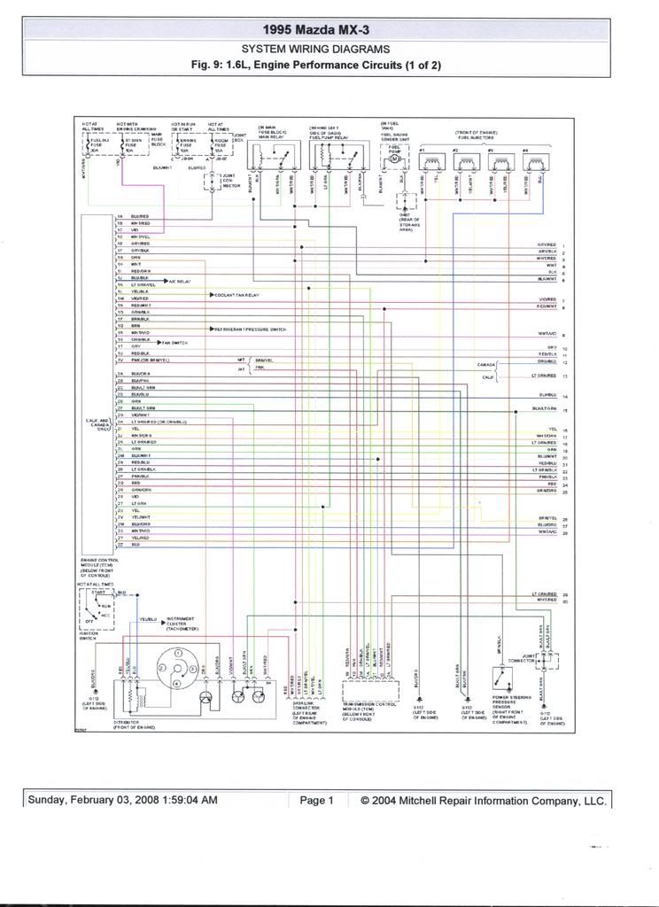
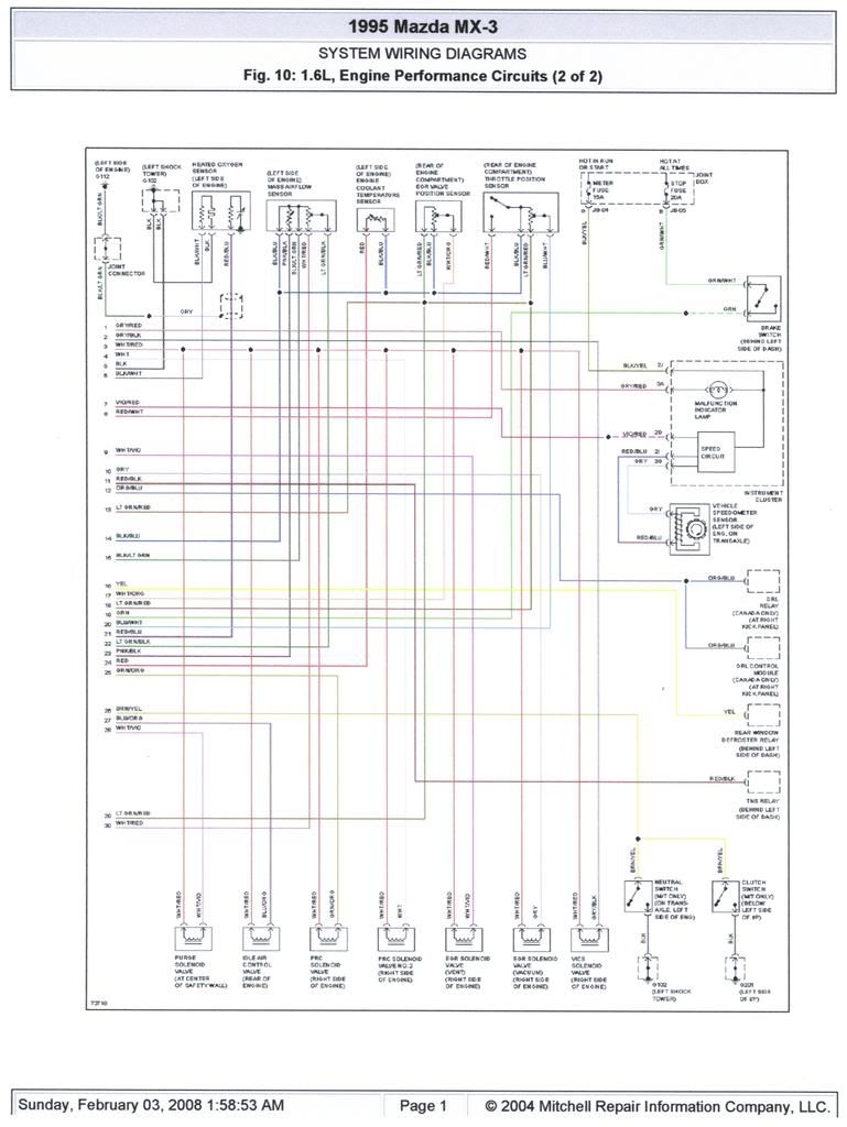
These are for '95. Sorry I couldnt screenshot them. The program wouldnt let me. I had to print and scan them. -doh-
-
RS_OBD'oh_2
- Senior Member
- Posts: 2400
- Joined: April 9th, 2007, 1:26 pm
- Location: Calgary, AB
Re: looking for dohc ecu wiring diagram
Hey man,
Ya, the 96 is vastly different when it comes to the ecu. Being it's only made in Canada in 96 and it's OBDII there are issues finding the wiring diagrams. I've hit up a few dealerships around my area and they don't even have them.
My ecu is a 3 plug. I started to "tone" out the pins using my telecom toner, set on continuity... didn't get very far... only tps and maf. Probably could have finished by now if I stuck to it.
Great to hear that someone else will be using the f/ic. It totally changes the meaning of "piggy back"
What set up do you plan on running?
Re: looking for dohc ecu wiring diagram
I have the 323 mani and a turbo off a Probe. Same IHI vj-11 rbh5? as far as I know. I used the Probe 280 injectors to get a bit more fuel. I don't have an intercooler yet and I'm only running 5.5lbs with the timing backed off a nudge. So yeh. It NEEDS the f/ic. I run the EMS in my Miata now and I love it. I checked into the schematic and couldnt find anything either. Do you think there's another car that might have that ECU like a 323 or Protege or something?
-
RS_OBD'oh_2
- Senior Member
- Posts: 2400
- Joined: April 9th, 2007, 1:26 pm
- Location: Calgary, AB
Re: looking for dohc ecu wiring diagram
I've tried to google the ecu part number B6gd 18 881B.. or whatevere it is. No matches. I think it might be used in the Euro mx-3's but I'm not too sure. I found a German site where you can buy the ecu's but I can't read german so.... ya.