Page 11 of 12
Re: Charlie's no budget mid engine build
Posted: September 25th, 2012, 12:48 pm
by Sleeper6
Are there provisions for that differential to be upside down? I would imagine that it would need to be kept covered in fluid to stay cool, if not thats a pretty spiffy idea.
Re: Charlie's no budget mid engine build
Posted: September 25th, 2012, 4:13 pm
by wytbishop
The ring gear is specifically designed to be mounted on either side of the diff so that it can be used for either mid engine or rear engine applications.
In the pic of the actually tranny I posted earlier in the thread the diff is inverted for a Ford GT40. Albins even makes inverted bellhousings for Ford and GM engines that use the factory starters.
Re: Charlie's no budget mid engine build
Posted: October 3rd, 2012, 9:38 am
by ethand
Wow, Charlie, I've just caught up on this again - you're really putting in the hard yards! Such awesome work, stoked to see you've kept at it & are applying all the research you've done. Awesome stuff.
Re: Charlie's no budget mid engine build
Posted: October 3rd, 2012, 9:56 am
by wytbishop
Thanks Ethan.
As often happens to me as soon as I posted my ideas for the rear subframe it occurred to me that many things were wrong with it. Total redesign is almost complete and I should have something to post tonight.
Re: Charlie's no budget mid engine build
Posted: October 3rd, 2012, 11:38 pm
by Nd4SpdSe
Re: Charlie's no budget mid engine build
Posted: October 4th, 2012, 10:00 am
by wytbishop
I have copies of the chassis and suspension chapters on my desktop. You will notice a likeness when you see the latest pictures. My control arms will be a sort of hybrid of the Pagani Zonda design and the Kirkham car's design.
Re: Charlie's no budget mid engine build
Posted: November 4th, 2012, 4:01 pm
by ethand
Any updates, Charlie?!

(sorry, just getting excited about this again! Hehe)
Re: Charlie's no budget mid engine build
Posted: November 4th, 2012, 7:27 pm
by wytbishop
I have been spending a lot of time (like over 400 hours now) modeling the rear subframe. Totally new design from what I posted previously.
It starts with a 2 piece adaptor system in which the adaptor plate also acts as the mounting point for the framework of the subframe.
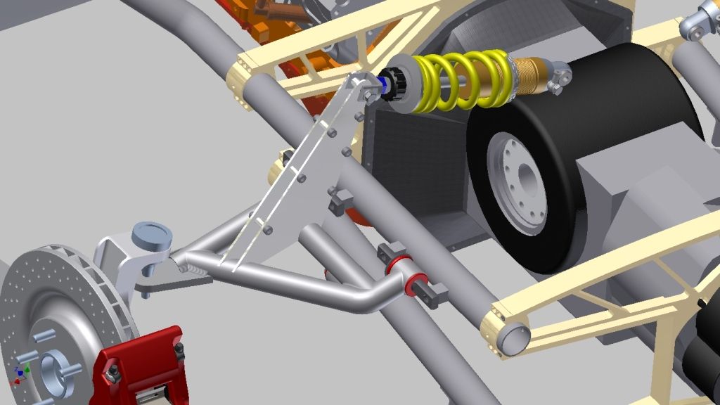
The upper control arms have the actuator cams for the shocks mounted directly on them so there is no push rod.
The rear mounting plate ties the tubular subframe together and will eventually be the mounting point for the rear fascia.
I still have to model the lower control arms and the base anchor for the shocks. The model in this image is very rough. The first step is just to determine where everything will go and the general position of things. Then I take the model apart and reproduce every part with accuracy. I'm in the middle of that process now.
At this point the suspension geometry is only rough as well. I'm trying to get a wheel motion ratio of about 1:1 and a wheel rate appropriate for a very lightweight, high horsepower, street going car.
Re: Charlie's no budget mid engine build
Posted: December 24th, 2012, 11:05 am
by wytbishop
Hey everyone, a little update. I have been working on modeling the rear subframe and suspension for about 4 months now. I believe I now have a concept that will work.
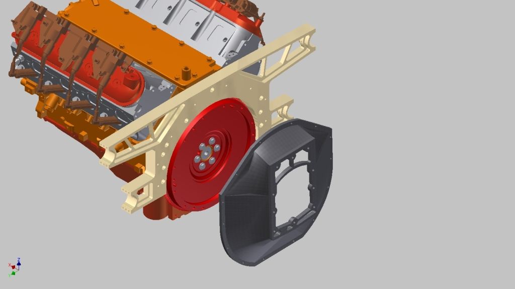
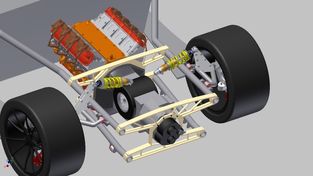
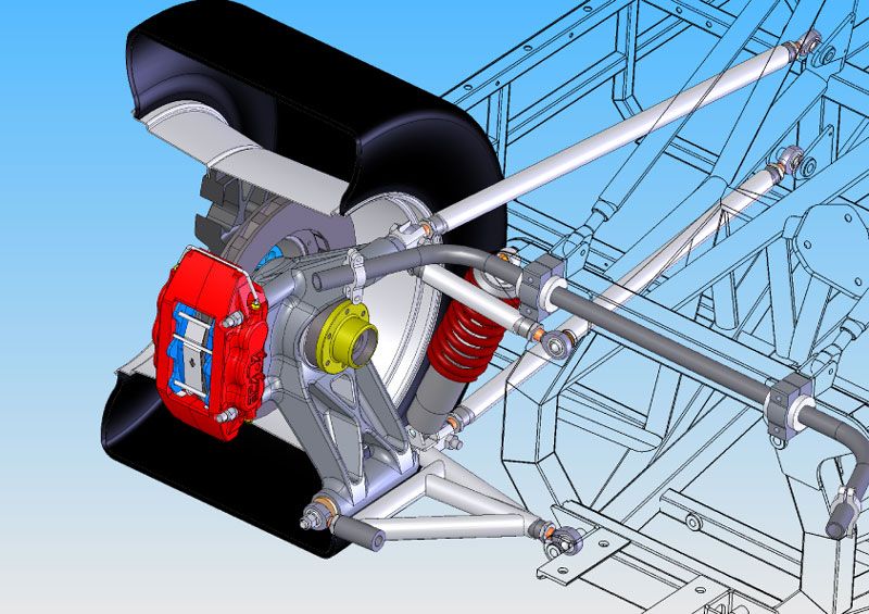
The bellhousing and engine adaptor plate have not changed...
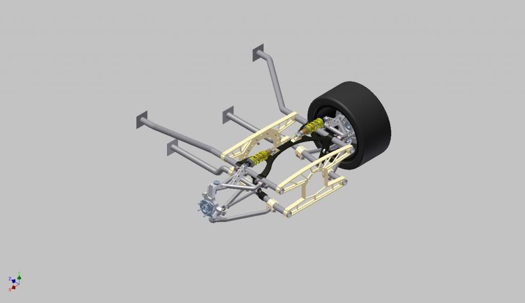
Here is the basic subframe with all the control arm mounts...
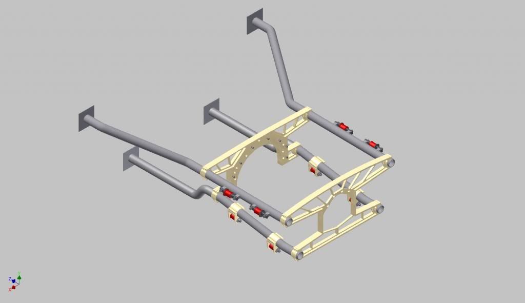
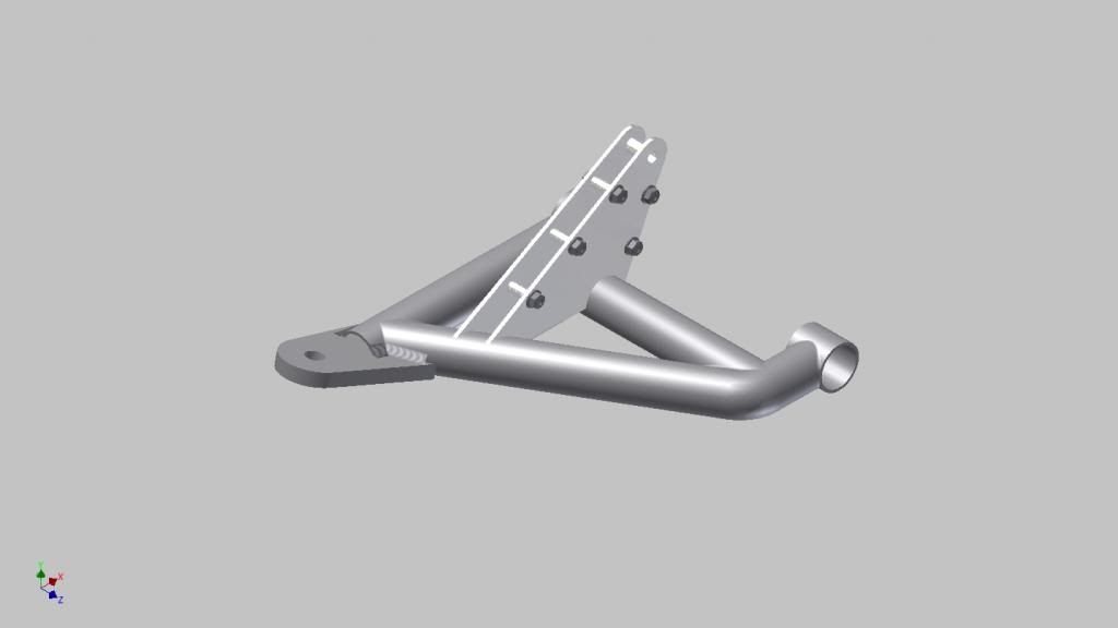
Here is the finished upper control arm...
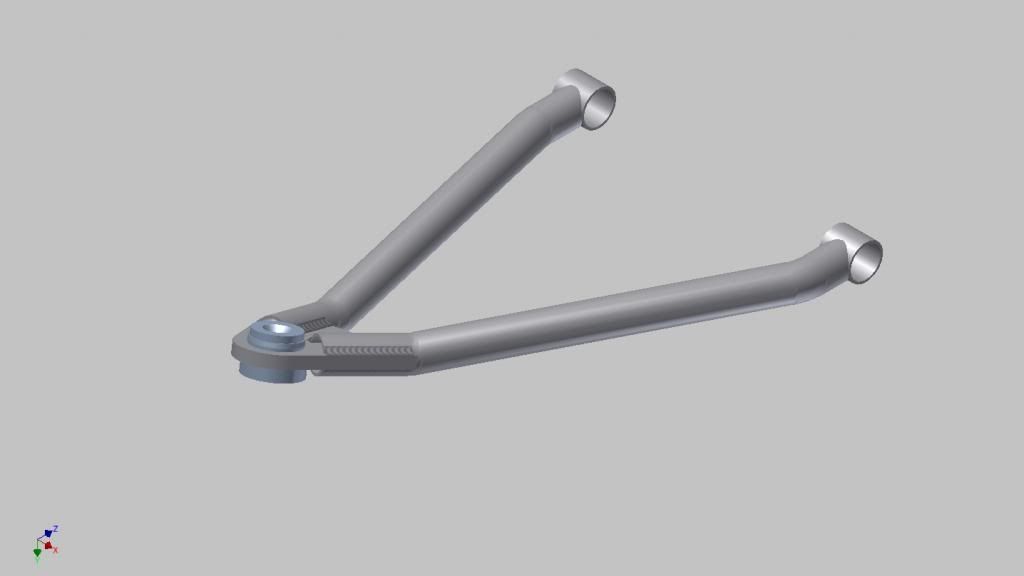
And lower control arm...
This is the shock mounting member which traverses the subframe overtop the gearbox. This provides a mount for the shocks and also significantly stiffens the subframe...
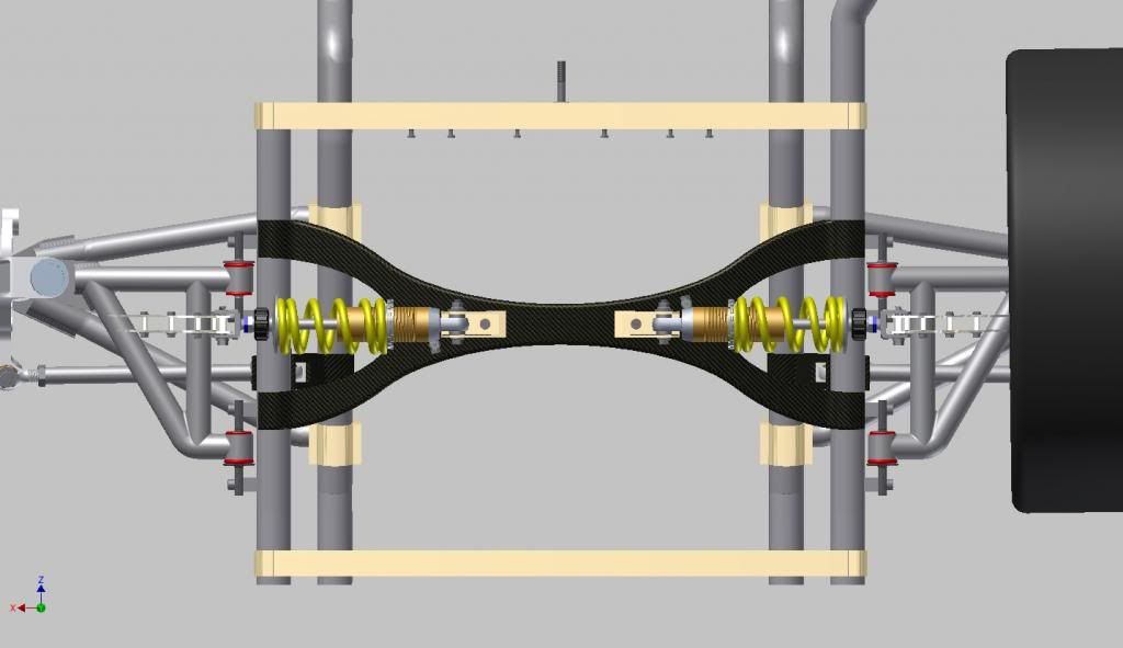
The hardest part so far has been identifying the pivot point of the rear toe link. I assembled the suspension and moved the upright through it's full travel plotting the position of the outer rod end at multiple points. Then I drew a curve in 3D space that corresponds to those points and found the center point of that curve.
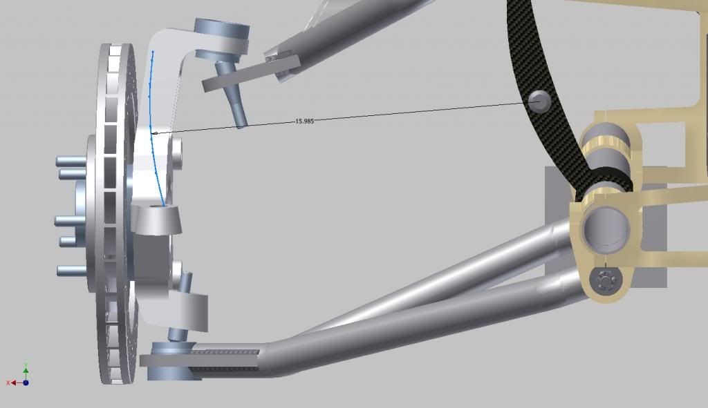
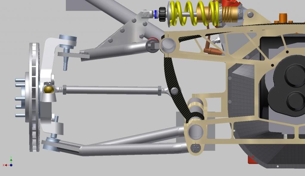
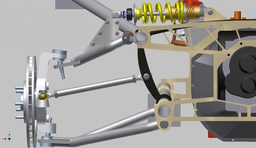
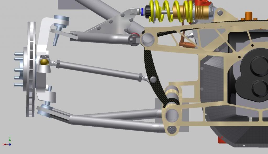
That is the position of the inner tie rod end. From there I modeled a mount for it, which again adds stiffness to the subframe and a tie rod to link the upright to the frame and I get this...
...at ride height...
...at full sag...
...and at full bump...
So that's where I am at the moment. I will have to put together an anti-sway bar of some kind. I'm kicking around a couple of designs in my head. I will need motor mounts but if I were ever to actually build this thing I would design them in place anyway so I'm not going to model them.
Now I will start on the front in the new year.
Re: Charlie's no budget mid engine build: *Codename:BlakBish
Posted: December 24th, 2012, 5:28 pm
by Evo_Spec
awesome work man!
Re: Charlie's no budget mid engine build: *Codename:BlakBish
Posted: December 31st, 2012, 2:50 pm
by kulluminati777
Very cool work!
I see you have wytbushings in the control arms lol j/p
Re: Charlie's no budget mid engine build: *Codename:BlakBish
Posted: December 31st, 2012, 2:59 pm
by Nd4SpdSe
With that rear suspension setup, it look like you could design a rear-steering setup, or if you could incorporate a type of passive system like the Mx3/Rx7 did
Re: Charlie's no budget mid engine build: *Codename:BlakBish
Posted: December 31st, 2012, 4:26 pm
by wytbishop
Evo_Spec wrote:awesome work man!
Thanks!
kulluminati777 wrote:Very cool work!
I see you have wytbushings in the control arms lol j/p
The best part of the Vette suspension is there are limitless options in the aftermarket. I don't have to design bushings. Lots of people have already done it.
Nd4SpdSe wrote:With that rear suspension setup, it look like you could design a rear-steering setup, or if you could incorporate a type of passive system like the Mx3/Rx7 did
I think part of why GM used the same spindles front and rear is to take advantage of the small unavoidable Caster and Toe-In gain that you get from a set up like this. When the outside wheel is compressed it naturally toe's either out or in depending on how you adjust the toe link and where the pivot is located. The way I have it set in these views, it is slightly toed in at ride height and becomes almost perfectly neutral at full bump. Down the road I plan to purchase the Suspension Analyzer software and fine tune things a bit.
Re: Charlie's no budget mid engine build: *Codename:BlakBish
Posted: December 31st, 2012, 6:35 pm
by Daninski
Great work Charlie. I was a little concerned about one aspect of your design. With the considerable forces acting to pull the wheel forward during acceleration or aft while braking would additional strength as seen in the below pic's double longitudinal support bars be a consideration?
Again, nice to see some progress. Cheers and Happy New Year.
Re: Charlie's no budget mid engine build: *Codename:BlakBish
Posted: January 1st, 2013, 9:01 pm
by wytbishop
Daninski wrote:With the considerable forces acting to pull the wheel forward during acceleration or aft while braking would additional strength as seen in the below pic's double longitudinal support bars be a consideration?
Notice that the design you posted doesn't use wishbone control arms, but each link has a single pivot point on a spherical heim joint. My design uses A-Arms.
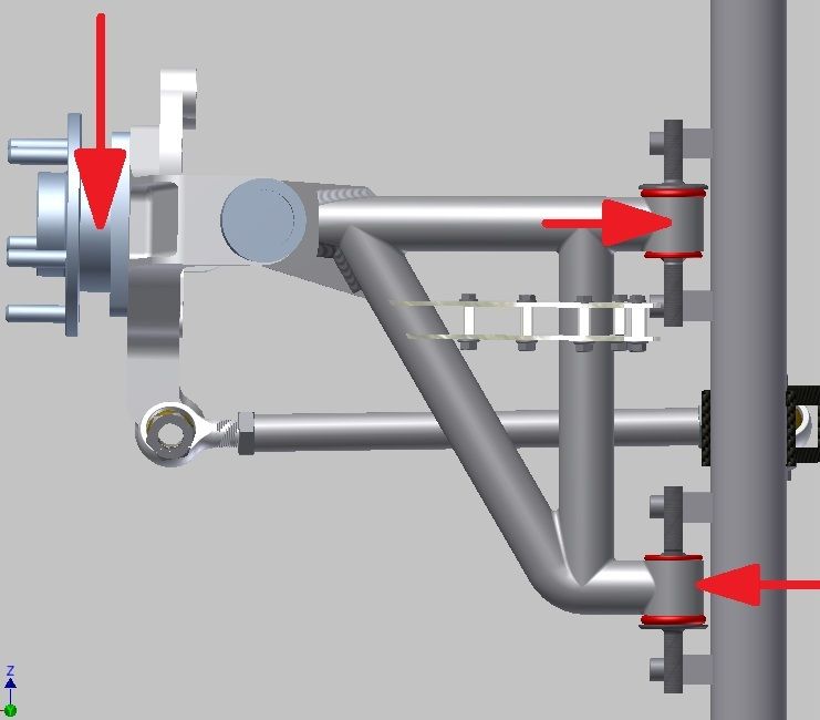
The forces fore and aft are absorbed by the bushings. The better the bushings, the less the control arm moves.