How To: KLZE Distributor installed on K8

V6 Technical/Performance Discussions
Post Reply
wytbishop
Senior Member
Posts: 5554
Joined: August 25th, 2004, 2:01 am
Location: Edmonton, Alberta, Canada

How To: KLZE Distributor installed on K8

Post by wytbishop »

I just completed installation of the ZE dizzy I bought from FieroMX. To my surprise and joy it fired up and ran perfectly on the first attempt.

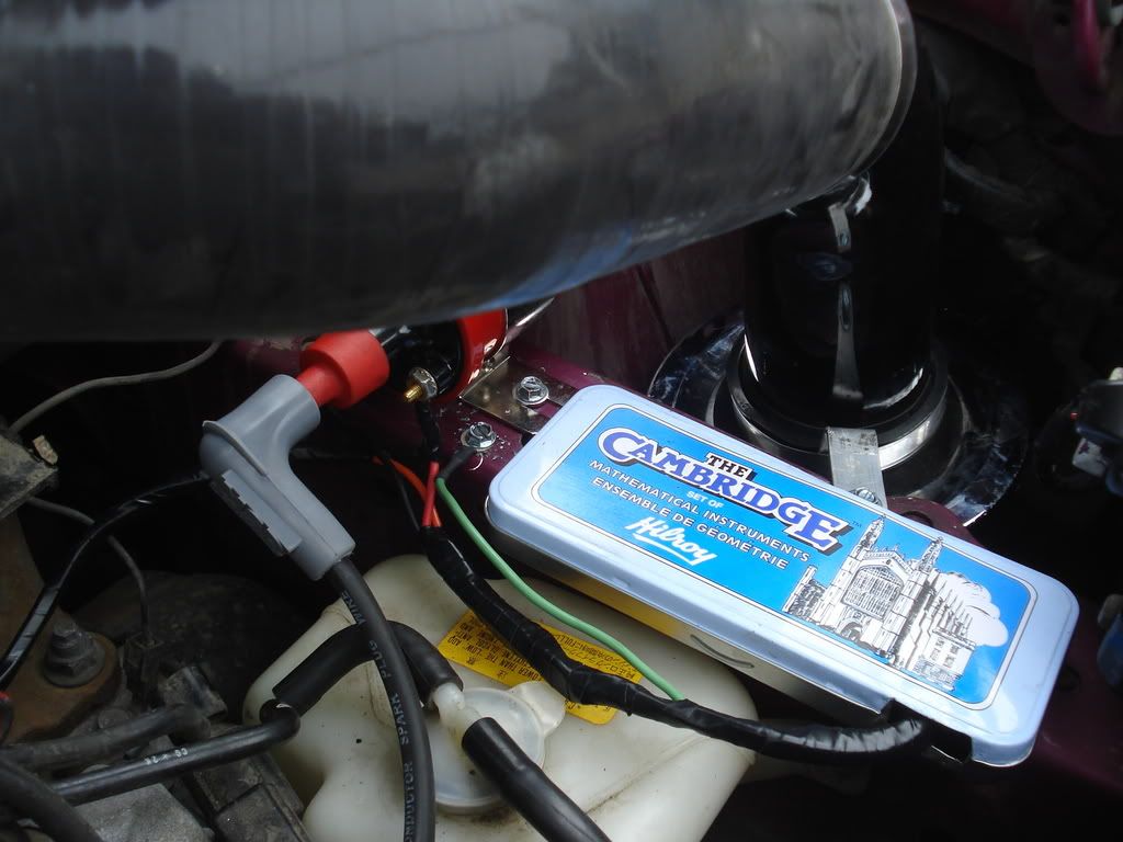
Now I'm super weird about things looking stock or at least clean in my engine compartment and I wasn't comfortable leaving the HEI module out in the open. So I was trying to find a way to both hide and protect the module and make the entire install look cleaner. I went to the local WalMart and scoured the store for something I could use as a case for the HEI that was metal and large enough to hold it and the associated wiring. I found a $4 geometry set like you used in grade school with the compass and the protractor and stuff. It's perfect.

Image

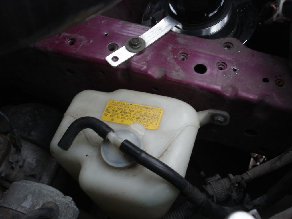
First I had to determine where I was going to mount everything. I had recently installed my cold air intake and relocated the coolant reservoir down on the frame rail...

Image

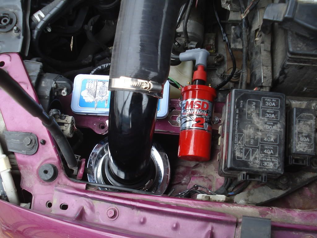
...so I figured I would just move the bracket I made for the air filter and mount my HEI box and Coil to the top of the frame rail...like this. The dizzy came with a coil, but I didn't like the way it looked so I got this Blaster 2. I like it much better and it fits really nicely.

Image

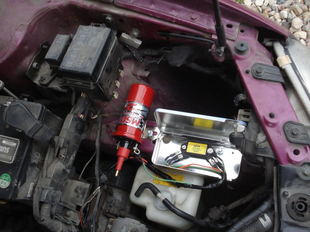
The HEI module is fastened to the box with 2 #10x3/4" countersunk head machine screws. The countersunk head of the screw ensures that the metal of the case is in contact with the body of the module. For mounting things I bought a pack of 1/4" tapping sheet metal screws and some flat washers. These are awesome because you just drill a 5/32" pilot hole and then screw them down and they hold very securely.

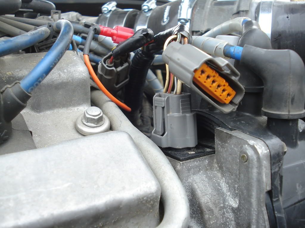
Now that I know where everything is going to go I can start building my wire harness. This took some time and a little trial and error. I wanted to do as little damage as possible to the stock wiring so I went to the parts yard and searched a couple cars until I found a male 3 pin and a female 4 pin connector. I got the 3 pin from the turn signal of a probe and I got the 4 pin off the dizzy of a protege I think. The generic HEI mod instructions require that the +ve and -ve leads of the coil and the tach signal wire go back to the 3 pin connector that used to be plugged into the stock distributor. This is true whether you're using the stock cap or a ZE cap if you're adding an external coil. Using the 3 pin connector allows me to plug the new harness to the 3 pin connector that used to be plugged into the stock distributor rather than cutting it off.

Image

The 4 pin plugs into the ZE distributor. Instead of just removing the 6 pin connector, I spliced the 4 pin connector with it...so now I have both.

Image

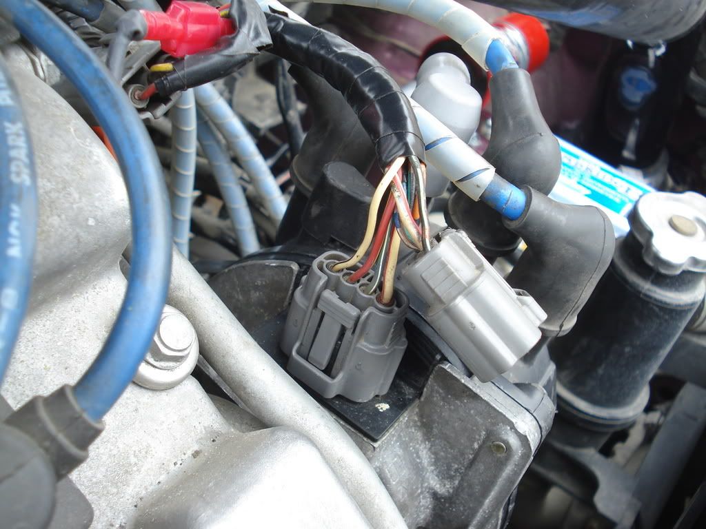
If something goes wrong I can unplug the 4 pin from the ZE dizzy and disconnect the trigger wire to the HEI module and be back on the stock distributor in about 3 minutes.

Harness Building Tips
Soldering iron. A larger one is better because when you twist a few wires together they actually become tough to heat up with a pencil iron.

Electronics solder. If you try to do this with heavy tin/lead solder you will wind up with crappy looking joints. Get the finest electronics solder you can get from Radio Shack.

Crimp on connectors. I use the crimp on connectors and I pull the insulation off. Crimp the connector onto the wire and then solder to be certain. My harness required 4 ring connectors (2 for the coil leads and 2 for the ground wire), 4 female blade connectors (for the HEI terminals) and 1 female/male blade connector pair (so that the orange trigger wire can be disconnected).

Heat Shrink Tubing. 3/16" diameter tubing works for almost all the connections you'll have to make. Anything larger won't shrink enough on smaller joints and 1/8" is too small for more than single wire twists.

Electrical Tape. You can use funky colors if you want. I like black.

The harness is not a very complex one. Here's the best description I can offer...I wish I had taken pictures while I was working on it.

Starting with the W terminal. Solder a female blade connector to the wire and cut off about 8" of wire. Solder a ring connector to another piece of the same color wire and cut off about 6" from that one. This ring connector is going to the body of the HEI module, so I secured it to the screw and plugged the blade connector to the W terminal. I ran the wires out of the opening I made in the side of the case and trim them to an equal length. Strip the ends and twist them together. Solder a second ring connector to a third piece of the same color wire. This will be the ground to the frame. Decide where you're going to ground it, and cut the length necessary to run it back to the first 2 wires you made. Solder all 3 wires together and that's the first part of the harness.

The G terminal. This is the easiest. Solder a female blade connector to a different color wire. I happened to have orange. I left lots of length to these wires so that I could test fit the harness before cutting them to final length. On the other end of the orange wire I crimped a female blade connector and then I crimped a male blade the the orange wire of the 6 pin connector of the distributor. I'll talk more about that later.

The B terminal. I start by soldering a female blade connector to a black wire. Connect it to the module and run it out of the case to the approximate position of the +ve post on the coil. Cut it and strip it. Take a second long length of black wire and strip one end and twist them together and crimp and solder on a ring connector. So positive will go from the HEI unit to the positive coil terminal and then on to the 3 pin connector. As with the orange wire, leave it long until you test fit.

The C terminal. This is the trickiest. In the diagram in the FAQ it shows the yellow tach signal wire branching off the red negative coil wire downstream from the coil, but electrically it makes no difference where these wires meet. So I started with a single red wire with a female blade connector coming from the case to the ring connector of the -ve terminal of the coil. From the coil -ve, 2 wires, a red and a white (because I didn't have yellow wire) go back to the 3 pin connector. This is a tough solder joint because you have 3 wires in that ring connector. About 6" from the coil -ve ring connector, I cut the white wire and spliced in the 1000ohm resistor. The resistor is EXTREMELY fragile. It has a single 20 gauge wire on each end. Treat it carefully. After soldering it in, I actually put 2 layers of heat shrink over it to keep it from being bent.

So you have a total of 4 wires going back to the distributor: Orange = HEI trigger signal, White (yellow in the diagram) = tach signal, Black (blue in the diagram) = coil +ve and Red = coil -ve.

Unplug the 3 pin connector from the stock distributor. Three of your four wires will connect to this connector using the female 3 pin connector taken from the auto wrecker. Determine the routing you like and cut these three wires to length. Then it's just a matter of soldering each wire to the correct wire on the female connector. When you're taking the connector from wherever you find it, make sure to leave as much wire on it as possible. It's obvious I know, but if you have trouble, you may have to trim and believe me you run out of wire fast.

I left the orange wire a little longer than the other 3 because it goes tot he 6 pin connector which is a couple inches farther away.

The 6 pin connector has to be cut. There's no way around it. I searched wiring diagrams looking for a female 6 pin connector anywhere on several cars, but to my knowledge there isn't one. I wanted to build a short patch harness from the stock 6 pin to the 4 pin I'm using to plug into the ZE dizzy. This was just in case things didn't work I'd still be able to run the stock unit until I sorted stuff out. My alternative solution was to cut it off, and solder it back on WITH the 4 pin connector.

NOTE: On the stock distributor the locating tab of the 6 pin connector is facing up, but on the 4 pin connector of the ZE dizzy, the locating tab faces back. Just don't let it confuse you as to which wire goes where. The diagrams in the FAQ are correct, so just follow them.

ALSO NOTE: My car is a 93' which uses pin 3 in the distributor connector for the cam angle sensor. 95' (and up I assume) don't use this wire so I assume they would not have a 3rd pin at all, but I'm not sure. Just be aware that there's a difference in 95'+ cars.

Image

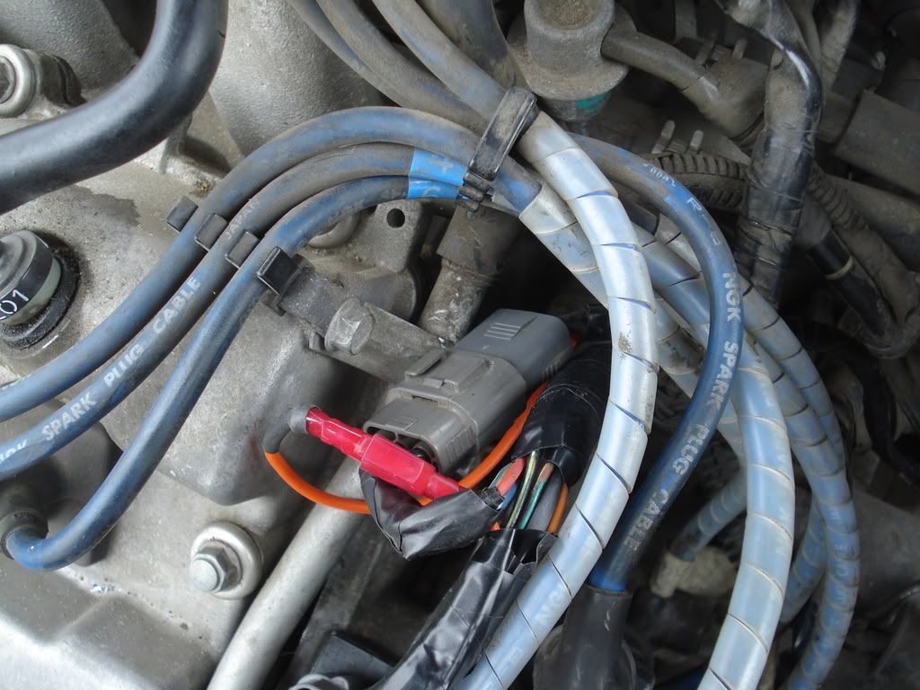
Pins 1-4 on the ZE dizzy go to pins 1-4 on the stock connector. Pin 5 is unused by the ZE dizzy but I reconnected it so that it will be there if I plug in the old dizzy. Pin 6 is the igniter trigger wire. I cut it, stripped the ends and twisted them back together with the orange wire that goes to terminal G on the HEI module, with the male/female blade connection in line. So if the 4 pin is plugged into the ZE dizzy, the orange wire gets connected to the HEI. If the 6 pin connector is plugged into the stock dizzy, disconnect the orange wire to the HEI and the internal trigger will still work.

Once the harness is done, just bolt the ZE dizzy to the head, plug the 4 pin connector to it, connect the 3 pin connector to your new harness, connect the ring terminals to the coil and you're all wired up. You'll need a coil wire, but this is pretty straight forward. I got a universal MSD coil wire kit and a power tower and it works fine.

I found 2 things of note with the ZE distributor. Terminals 4 and 5 are reversed on the cap. If connect 4o to 5 and vice versa, the car will run (mine did anyway) but very poorly for obvious reasons. Also, the points inside the cap are offset from the position in the stock cap...

Image

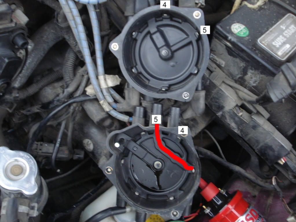
That's the ZE dizzy on top. I tried to put them in the same orientation for this picture and you can see that the points are not in the same position around the cap. This threw me off for a minute because when I put the rotor on it was not in the same place from the stock one I had just taken off. Not to worry though. It works exactly as it should.

Here is what it looks like finished...

Image

Image

Happy to answer any questions anyone has.
94' RS/GS/MS/CF Monster Turbo...coming soon.
93' GS SE, the Black Beast, the former love of my life...soon to be gutted and crushed.
94' GS, black on black, now in several small pieces...and one large crushed piece.
2007 Mazda3 GT Sport --- super fun
2004 Honda RC51 --- Lost forever to some theavin' bastard
My Worklog
My feedback thread
Never attribute to malice that which can be adequately explained by stupidity.
User avatar
V8KOMX3
Supporting Member
Posts: 911
Joined: August 8th, 2004, 2:01 am
Location: Wyoming

Re: How To: KLZE Distributor installed on K8

Post by V8KOMX3 »

I think that is a great write up. I'm not much for your Cambridge box, but I will give you props because that is creative. Good Work
Teal 1993 MX3GSZE
wytbishop
Senior Member
Posts: 5554
Joined: August 25th, 2004, 2:01 am
Location: Edmonton, Alberta, Canada

Re: How To: KLZE Distributor installed on K8

Post by wytbishop »

Thanks. I figured a lot of guys will say something like that. I plan to paint it red to match the coil.
94' RS/GS/MS/CF Monster Turbo...coming soon.
93' GS SE, the Black Beast, the former love of my life...soon to be gutted and crushed.
94' GS, black on black, now in several small pieces...and one large crushed piece.
2007 Mazda3 GT Sport --- super fun
2004 Honda RC51 --- Lost forever to some theavin' bastard
My Worklog
My feedback thread
Never attribute to malice that which can be adequately explained by stupidity.
User avatar
Daninski
Supporting Member
Posts: 7055
Joined: June 18th, 2007, 10:51 am
Location: Trenton ON.

Re: How To: KLZE Distributor installed on K8

Post by Daninski »

With the geometry case being metal there could be an issue with condensation and eventual corrosion (IMO). A few vent holes in the sides may protect against condensation and just for the sake of arguement. Is there any heat involved?
2004 Subaru WRX Silver, stage 2, minty interior.
2002 Subaru WRX Blue, SOLD (best E test numbers I've ever seen)
94 MX-6. Sold
92 GS KLZE 5 Speed
96 GS 5 speed, KLZE, Sold
95 GS Minty Shape Sold
92 GS Sold
92 GS Parts Car scrapped.
Feedback viewtopic.php?f=37&t=66348" onclick="window.open(this.href);return false;
7477th member.

I know you believe that you understand what you think I said but I'm sure you realize that what you heard is not what I meant.
wytbishop
Senior Member
Posts: 5554
Joined: August 25th, 2004, 2:01 am
Location: Edmonton, Alberta, Canada

Re: How To: KLZE Distributor installed on K8

Post by wytbishop »

the ignitor does get hot, but it's designed to live inside a GM HEI distributor so I figure it's at least no worse of in my tin box.
94' RS/GS/MS/CF Monster Turbo...coming soon.
93' GS SE, the Black Beast, the former love of my life...soon to be gutted and crushed.
94' GS, black on black, now in several small pieces...and one large crushed piece.
2007 Mazda3 GT Sport --- super fun
2004 Honda RC51 --- Lost forever to some theavin' bastard
My Worklog
My feedback thread
Never attribute to malice that which can be adequately explained by stupidity.
User avatar
Mooneggs
Forum Moderator
Posts: 6128
Joined: August 10th, 2005, 10:08 pm
antispam: ~SPAM*SUX~
Location: Hillsboro, OR
Contact:

Re: How To: KLZE Distributor installed on K8

Post by Mooneggs »

I thought that the msd blaster2 had to sit vertical?? :shock:

I have had my hei module exposed to the elements for some time with no problems... the box is cool I guess 8)
User avatar
Daninski
Supporting Member
Posts: 7055
Joined: June 18th, 2007, 10:51 am
Location: Trenton ON.

Re: How To: KLZE Distributor installed on K8

Post by Daninski »

I just installed my ZE and spent a lot of extra time to get things factory looking but when I hit the key it started up and has ran like sh*t ever since so consider yourself lucky (or skilled). I just want to drive mine but I'm now into a pretty indepth desnaging situation. It would be nice if someone posted ZE configuration pics that we could reference. You know like pics before then engine goes in. I'll try to take a few if I can get mine configured properly. Enjoy your ride now Dude :)
2004 Subaru WRX Silver, stage 2, minty interior.
2002 Subaru WRX Blue, SOLD (best E test numbers I've ever seen)
94 MX-6. Sold
92 GS KLZE 5 Speed
96 GS 5 speed, KLZE, Sold
95 GS Minty Shape Sold
92 GS Sold
92 GS Parts Car scrapped.
Feedback viewtopic.php?f=37&t=66348" onclick="window.open(this.href);return false;
7477th member.

I know you believe that you understand what you think I said but I'm sure you realize that what you heard is not what I meant.
User avatar
fowljesse
Supporting Member
Posts: 5676
Joined: March 17th, 2006, 2:59 pm
Location: portland, OR
Contact:

Re: How To: KLZE Distributor installed on K8

Post by fowljesse »

The module can fail, if it gets too hot. I've even seen a computer heat sink stuck to one, just in case. It looked really cool, too. I like the stealth look, but it may get too hot.
'93 GS - P&P DE w/ ZE exh. cams/ pistns, KLG4 IM, 65mm TB, MSnS, Phenos, K&N RAI, UDP, Grnd wires, rear batt, filld MM, torq strt, TWM short shftr, Exedy, Lng tube hdrs 2.5" Side exhaust, H&R sprngs, Poly bushngs, strutbars, Alum. crss mmber&tiebar, 22mm swybar, solid links, Direzzas, leather int, Alpine 9805 stereo & alrm, keyless entry, 10 Boston Accoustics spkrs, Prjectrs, Blaster2, CF hood, FG hatch, Lexan
User avatar
Daninski
Supporting Member
Posts: 7055
Joined: June 18th, 2007, 10:51 am
Location: Trenton ON.

Re: How To: KLZE Distributor installed on K8

Post by Daninski »

I have a big badas* copper heat sink from an nvidia 6800GT vid card I could rig up. That should keep things cool if I could do a voltage step down.
2004 Subaru WRX Silver, stage 2, minty interior.
2002 Subaru WRX Blue, SOLD (best E test numbers I've ever seen)
94 MX-6. Sold
92 GS KLZE 5 Speed
96 GS 5 speed, KLZE, Sold
95 GS Minty Shape Sold
92 GS Sold
92 GS Parts Car scrapped.
Feedback viewtopic.php?f=37&t=66348" onclick="window.open(this.href);return false;
7477th member.

I know you believe that you understand what you think I said but I'm sure you realize that what you heard is not what I meant.
Gods Father
Regular Member
Posts: 126
Joined: August 6th, 2007, 2:01 am
Location: Boston, Massachusetts

Re: How To: KLZE Distributor installed on K8

Post by Gods Father »

ok so about the spark plug wires...they still all wire up te same? or do you have to switch the 4 and 5 spots? because im doin the KLZE swap so i dont have to actually swap dizzys so should i even worry about that step?...thanks
1993 MX-3 w/ straight neck KLZE swap...Probe GT 2.5in headers, Custom exhaust w/ test pipe and OBX Twin Loop Tip, Bully Stage 3 Clutch, Fidanza Flywheel, Pheno Spacers, HEI mod, Blaster SS coil, Probinator chip, TWM short shifter, AWR front and rear mounts (88 Durometer), and Corksport braided clutch line...so far

Ever see the lone rider of the night? Well he'll find you and then you'll never him again...
RX8SE3P
Regular Member
Posts: 912
Joined: April 9th, 2007, 8:11 am

Re: How To: KLZE Distributor installed on K8

Post by RX8SE3P »

Nice stuff.

My ZE actually came with it's own disty. I have a HEI module so I guess all I need now is some MSD coil thing like you right?

I have a 1995 OBDI MX3. Do you think this will be difficult to setup?
1995 Eunos 30x KLZE
Worklog
wytbishop
Senior Member
Posts: 5554
Joined: August 25th, 2004, 2:01 am
Location: Edmonton, Alberta, Canada

Re: How To: KLZE Distributor installed on K8

Post by wytbishop »

Gods Father wrote:ok so about the spark plug wires...they still all wire up te same? or do you have to switch the 4 and 5 spots? because im doin the KLZE swap so i dont have to actually swap dizzys so should i even worry about that step?...thanks
Your ZE plug wires should already be routed correctly for the ZE disty.
94' RS/GS/MS/CF Monster Turbo...coming soon.
93' GS SE, the Black Beast, the former love of my life...soon to be gutted and crushed.
94' GS, black on black, now in several small pieces...and one large crushed piece.
2007 Mazda3 GT Sport --- super fun
2004 Honda RC51 --- Lost forever to some theavin' bastard
My Worklog
My feedback thread
Never attribute to malice that which can be adequately explained by stupidity.
wytbishop
Senior Member
Posts: 5554
Joined: August 25th, 2004, 2:01 am
Location: Edmonton, Alberta, Canada

Re: How To: KLZE Distributor installed on K8

Post by wytbishop »

RX8SE3P wrote:Nice stuff.

My ZE actually came with it's own disty. I have a HEI module so I guess all I need now is some MSD coil thing like you right?

I have a 1995 OBDI MX3. Do you think this will be difficult to setup?
Right. The ZE ignition system was born with external coil and ignitor. While the K8 users of the world have the option to continue to use the K8 disty's internal coil, you do not. If your MX-3 is OBD1, and you're using the stock wire harness you should be able to do exactly what I did. Get an MSD Blaster SS or similar non oil filled coil. They last longer and can be mounted in any orientation. The Blaster 2 I used in this write up fried because I mounted it on it's side.
94' RS/GS/MS/CF Monster Turbo...coming soon.
93' GS SE, the Black Beast, the former love of my life...soon to be gutted and crushed.
94' GS, black on black, now in several small pieces...and one large crushed piece.
2007 Mazda3 GT Sport --- super fun
2004 Honda RC51 --- Lost forever to some theavin' bastard
My Worklog
My feedback thread
Never attribute to malice that which can be adequately explained by stupidity.
User avatar
clearconscience
Junior Member
Posts: 13
Joined: June 14th, 2015, 8:39 pm
antispam: ~SPAM*SUX~

Re: How To: KLZE Distributor installed on K8

Post by clearconscience »

Good Evening to all,

I was had a couple inquiries. One is when you briefly describe pins 1-4 off the stock connector are you reffering to the 6 pin connector from the original wiring harness and from what direction front of car to rear or rear of car to front? Also, when installing a power tower to the blaster 2 coil ive read on some hot rod forums that in order to secure it you thread the top terminal onto the screw in the receptacle of the coil.

Lastly Is there a wiring diagram for a ZE disty conversion?
<a href="http://www.freeimagehosting.net/commerc ... phy/"><img src="http://i.imgur.com/Ebelrp3.jpg" alt="commercial photography locations"></a>
Post Reply

Return to “V6 Technical/Performance”