Page 1 of 2
Megasquirt and the b6 sohc Distributor
Posted: July 29th, 2006, 4:16 pm
by Bochek
this might be a bit of a tricky question. when using msns-e how do i go about configuring it with a Distributor and a MSD 6A? i cant see it being too complicated.
Our distributor's are electronic advance correct.
a bit of schematics or wiring help would be appreciated here.
thanks,
Bochek
Posted: July 29th, 2006, 4:49 pm
by Bochek
my chiltons manual says that all n/a b6 and bp engines are traditional electronic ignitions (vaccume and centrifugal advance)
if that is true then what are the 4 wires going into the top of the disty?
Bochek
Posted: July 29th, 2006, 11:01 pm
by ryanlindenberg
this is for a BP disty, but the B6 could be the same:
Black/Light Green = Ground
White = Trigger Signal
Yellow/Blue = Home Signal
White/Red = +13.8 Volts
My Haltech wired into the 4 wires on the disty, then i ran my Haltech Ignition Output wire to the white Trigger wire on the 6A. after that just wire up your coil to the 6A and voila!!! I assume the MS&S would be very similar.
Posted: July 29th, 2006, 11:04 pm
by Bochek
well i guess im going to have to do some wicked research on the outputs for controlling a disty with msns.
Posted: July 29th, 2006, 11:09 pm
by Bochek
also, what is the home signal,
i think i under stand the trigger signal, it tels the ecu when to fire the coil, right, its sorta like your hall effect sensor, or VR sensor or w/e its called.
if all this is true, then the home signal must advance the disty's timing?
im sure this cant be that complicated.
Bochek
Posted: July 29th, 2006, 11:10 pm
by ryanlindenberg
you don't really control the disty, you just get a signal from it telling you the position of the engine. this signal will go to your MS&S. then the MS&S tells the MSD 6A when to fire the plugs.
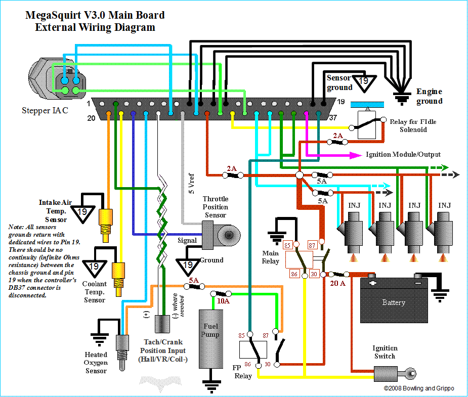
is there a wiring diagram for the MS&S that you could link to or post...that would help a lot.
Posted: July 29th, 2006, 11:13 pm
by Bochek

not exactly the same, as that is MS-II and i am running MS-I MSnS-E
But its basically the same
Posted: July 29th, 2006, 11:14 pm
by Bochek
ok well something must advance the disty's timing correct, is it mechanical? it it was you think you would see a vaccuume line going to the disty.
Posted: July 29th, 2006, 11:24 pm
by ryanlindenberg
Well your 6A would wire up to the brownish "Ignition Module/Coil Control" wire (hook up to the white 6A wire).
for the disty you could try something like this
Ground the Black/Light Green wire to the chassis.
Connect the White disty wire to the (-) MS&S wire
Connect the White/Red disty wire tot the MS&S (+) wire.
i don't know for sure if that would work or not...i don't know much about the MS&S.
Posted: July 29th, 2006, 11:30 pm
by Bochek
well its a starting point, as soon as i get my hands on a graphing volt meter or scope il be able to be more sure about it, thanks for your help so far.
if anyone else knows anything about the b6 sohc disty, SPEAK UP PLEASE!
Bochek
Posted: July 29th, 2006, 11:31 pm
by ryanlindenberg
the ecu would be controlling the timing. the mx-3's (at least the DOHC) have internal coils. the ECU would electronically be telling the coil to spark later or earlier (retarding or advancing the timing). the amount of timing is based on a lot of things such as engine load, air temp, coolant temp, RPM, etc...
if you look at your rotor, you will notice that the contact area is very large. this is so that the timing can be adjusted electronically over a wider range of engine position.
when you run an MSD, that is what controls the coil. and your MSD listens to what your MS&S tells it to do. this eliminates whatever your internal coil was doing earlier. so all your stock disty is used for is to determine engine position, and to spin the rotor in the cap.
Posted: July 30th, 2006, 1:31 am
by ariesdude
The SOHC has external coil disty - The home signal will give the exact position of the 1st cylinder at all times and trigger occurs after that (i think). For controlling the timing the ecu doesnt have to rotate the disty. The ecu just tells the coil when to fire - there is a huge chunk of time (relatively) where the rotor is close to the ignition points on the cap. (The rotor and contacts never touch - the high voltage can arc thru air).
The MS diagrams may not be completely applicable here - our distys use hall effect sensors not reluctors....
Posted: July 30th, 2006, 7:40 am
by Bochek
ariesdude wrote:our distys use hall effect sensors not reluctors....
THANK YOU!!!!! thats the first thing i needed to know, i have the diagrams somewhere for hall effect sensors!
so wich signal would i use? home or trigger? im assuming the trigger signal.
Bochek
Posted: July 30th, 2006, 7:48 am
by Bochek
so then this would be the wiring diagram i would be looking at:

Harness -- Diagram
white/red -- red
black/light green -- black
whitte -- green
yellow/blue -- not used
and this would be the diagram for connection the 6A

yay, i think we got it
Thanks alot everyone!
now its just time to order the megasquirt.
Bochek
Posted: July 30th, 2006, 9:47 am
by Bochek
so just checking...
in this picture

from left to right we have
ground
+12vdc
trigger
home
Thanks,
Bochek


